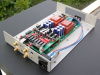
I am currently building Miha Rauta's FC-100 amplifier.
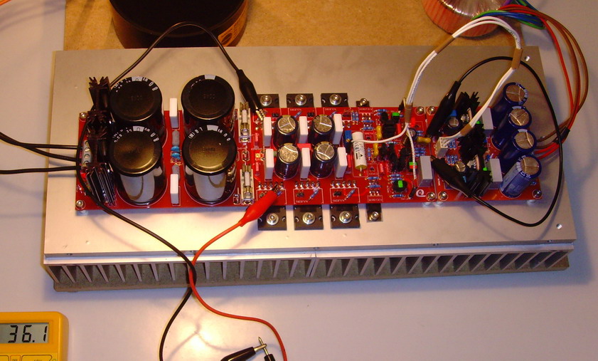
Both channels work as designed, and I fastened them on the bottom plate of the ALU case.
Since I need some space for additional components (source selector, attenuation,...):
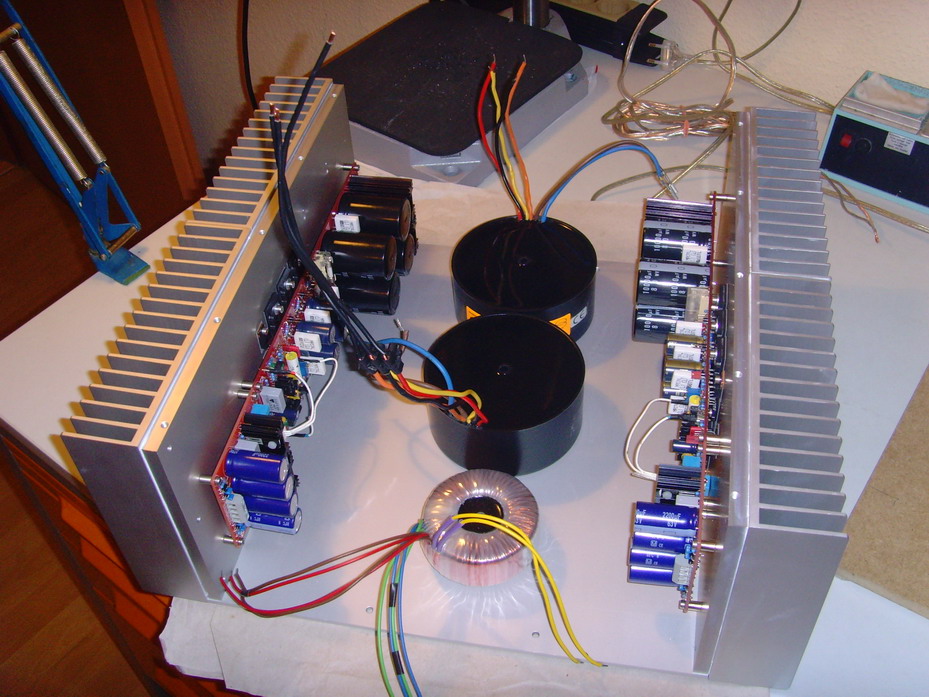
Shall I install the transformers one behind the other (as shown on the picture above), build some metall cage around them
and install the additional PCBs on the "first floor", or shall I stack the big black transformers one above the other?
Is there any recommendation what to do and what to do not?
Best regards - Rudi_Ratlos
Both channels work as designed, and I fastened them on the bottom plate of the ALU case.
Since I need some space for additional components (source selector, attenuation,...):
Shall I install the transformers one behind the other (as shown on the picture above), build some metall cage around them
and install the additional PCBs on the "first floor", or shall I stack the big black transformers one above the other?
Is there any recommendation what to do and what to do not?
Best regards - Rudi_Ratlos
SPEECHLESS......
yess agree
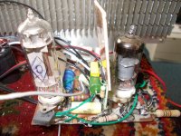
I have to build soon a case for the hybrid amp, after the pcb,s are ready afcourse, a type where the tubes can be seen on the above the front and or behind glass or plastic window, like this
The NEW Moscode 402Au Tube Hybrid Amplifier
Link as example for window, the other has the tubes up with cooling profile mosfets behind it.
Attachments
Last edited:
I have to build soon a case for the hybrid amp.......
is that a 6C19n ?
could I see a schematic of the tube section ?
or anything you know about this tube
PM if you like/prefer
Shall I install the transformers one behind the other (as shown on the picture above), build some metall cage around them
and install the additional PCBs on the "first floor", or shall I stack the big black transformers one above the other?
Is there any recommendation what to do and what to do not?
Best regards - Rudi_Ratlos
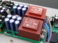
How powerful are they? I find the talema/nuvotec potted transformers to be very quiet and decently shielded.
I would mount one above the other. Not sure of the little one.
Perpendicular respect the signal pcb is already the correct way 🙂
Telstar,
the Talema transformers are 2 x 25 VAC / 225W each.
The small transformer is 4 x 34 VAC / 50W and supplies the frontend-shunts with power.
Best regards - Rudi_Ratlos
the Talema transformers are 2 x 25 VAC / 225W each.
The small transformer is 4 x 34 VAC / 50W and supplies the frontend-shunts with power.
Best regards - Rudi_Ratlos
is that a 6C19n ?
could I see a schematic of the tube section ?
or anything you know about this tube
PM if you like/prefer
here the sound, as a idea, youtube is not so well sounding, also because I did only use a mid speaker with own little closed box and tweeter, but soundstage is big, it was a test to listen to platefollowers only. and yes, it sounds much relaxed, and special it give better bas.
real diy testing, real fun. - YouTube
Attachments
what and what not?
Whichever is easier ?
Personally, i find fully resin encapsulated tranformers less practical than regular toroidals, due to the wires sticking out from the bottom.
Plenty commercial examples of stacked transformers, with/without a metal pan cover (e.g. Threshold monaurals)
If capacitor can height isn't the issue, a double-decker is easier, having an alloy metal plate folded to size is also cheaper than buying a (tall) transformer cover.
(there was a time when me used cheapo aluminum camping cooking pots as transformer covers, only takes a can of black spray paint)
Last edited:
well done Professor - nice wooden enclosure!
My JLH boards is still waiting when i solder them 🙄
My JLH boards is still waiting when i solder them 🙄
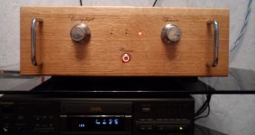
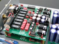
My new phono preamplifier design. The case and controller PCB (the one at the front) are temporary while I finish the design.
Attachments


here the sound, as a idea, youtube is not so well sounding........
thanks
best sound clip yet 😉
but pics of amp not so good 😀
Hello amc184. That is the most complicated phono section I have ever seen. Any chance you could explain what is going on in each board and what design philosophy you were using?
best sound clip yet 😉
the sound reminds me, you have shown it before
reminded by the sound of a you tube clip
hehe, thats kind of funny 😛
The two stacked boards at the rear are the signal PCBs, each is one channel and has an MC amp, an EQ amp and a positive and a negative discrete regulator. The EQ stage has an adjustable filter, and can equalise LPs using the RIAA, AES, FFRR and NAB curves. Four of the reed relays are used to switch the filter, the other three select or bypass the MC stage. The 8-way DIP switch selects the cartridge loading and gain. The MC amp uses a LT1115, the EQ stage uses an OPA134 and BUF634 (I might change the OPA134).
The middle board is the power supply, and outputs four isolated 0-21VDC rails. They're connected on the signal boards to provide an isolated +/- 21VDC supply for each.
When finished, there will be a control PCB and a switch / display PCB at the front with an independent transformer and supply based on an Arduino Nano. I've not finished it though, so at the moment there's just a DIP switch, a regulator and a 9V battery to allow me to power the relays.
It sounds really good, especially with Deutsche Grammophon LPs using the AES curve. I gave it a good test last weekend using a Pro-Ject RPM9 with an Ortofon MC Rohmann cartridge.
AMC184 thats an excellent job you have made of that phono 😉
Did you design and build the PCBs yourself?
Alan
Did you design and build the PCBs yourself?
Alan
Excellent! Looks great. It's obvious the attention to detail paid to your build. I'm sure it sounds as great as it looks.My new phono preamplifier design. The case and controller PCB (the one at the front) are temporary while I finish the design.
best sound clip yet 😉
but pics of amp not so good 😀
Quality of pics doesn't matter!
Indeed, a very impressive sound!😱
Congrats, Kees!
Did you design and build the PCBs yourself?
I did both the circuit and PCB design. I had the PCBs made by Seeed Studio ($65 for 10 each of all the PCBs in the photos) and assembled them myself. The case I had lasercut and bent by a local sheetmetal shop.
- Home
- Amplifiers
- Solid State
- Post your Solid State pics here