My new baby named CHARISMA
With each humility i present 3 pictures of my dream for enough years which is my new project after an exhaustive work of 5 months.
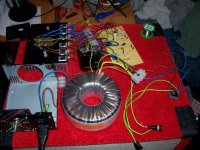
Who is the Charisma? It is a stereo (dual mono arrangement with individual supplies for each channel) preamplifier whole of discrete devices consisted from two units. The first includes the power supply, the microcontroler unit and the big LCD display. It is a fully remotely controllable system. The second unit comprises the main analog stereo preamplifier; this includes 7 inputs: one phono, two balanced for CDs or DACs, two single for CDs or DACs and finally two single line level inputs. It is obvious from the photos the different input filtering arrangement for each type of source, and this is exactly the charisma of this project; when one source it is connected all the other sources are absolutelly inactive. With other words, this preamplifier works as a seven seperate sources, once per time. The outputs are: one direct record after the main buffer or the individual phono preamplifier but before the volume control, as well one balanced and two single outputs. The outputs are absolutelly seperated between them via the output mute relays.
Another one remark it is the absolute absence of any cable connection. I hate cables, thus i have spend a lot of time during the designing of PCB layouts.
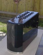
The photos presents only the main board of the analog preamplifier unit. In the 2nd photo taken from the front, it is obvious the empty holes which addressed for the chassis mounted RCA or Phono sockets as they are all of the high quality type.The heart of the unit which are the seperatelly assembled discrete operational amplifiers they are ready but under examination at this moment on the workbench for taking measurements. After 2 days i will post photos of the completted analog unit. After one week also i will post the photos of the controll-power supply unit.
A meaningfull remark: all the PCBs are double sided and LITERALLY home maden from my hands. It is obvious the trick of the soldered wire jumpers to bridge the tracks from the component side to the solder side. This is reported to encourage you, to make (with few and inexpensive means) your own PCBs at home. For the record: The cost of these PCBs maden in a laboratory it is about 150 Euros. The total size of the PCB (which comprised from 2 seperate and bridged with gold pins between them PCBs of 190mm X 270mm each) it is 380 X 270mm. Instead the cost of these home maden PCBs it is about 25 Euros. For any information and help, i am available as usually.
Fotios
With each humility i present 3 pictures of my dream for enough years which is my new project after an exhaustive work of 5 months.
Who is the Charisma? It is a stereo (dual mono arrangement with individual supplies for each channel) preamplifier whole of discrete devices consisted from two units. The first includes the power supply, the microcontroler unit and the big LCD display. It is a fully remotely controllable system. The second unit comprises the main analog stereo preamplifier; this includes 7 inputs: one phono, two balanced for CDs or DACs, two single for CDs or DACs and finally two single line level inputs. It is obvious from the photos the different input filtering arrangement for each type of source, and this is exactly the charisma of this project; when one source it is connected all the other sources are absolutelly inactive. With other words, this preamplifier works as a seven seperate sources, once per time. The outputs are: one direct record after the main buffer or the individual phono preamplifier but before the volume control, as well one balanced and two single outputs. The outputs are absolutelly seperated between them via the output mute relays.
Another one remark it is the absolute absence of any cable connection. I hate cables, thus i have spend a lot of time during the designing of PCB layouts.
The photos presents only the main board of the analog preamplifier unit. In the 2nd photo taken from the front, it is obvious the empty holes which addressed for the chassis mounted RCA or Phono sockets as they are all of the high quality type.The heart of the unit which are the seperatelly assembled discrete operational amplifiers they are ready but under examination at this moment on the workbench for taking measurements. After 2 days i will post photos of the completted analog unit. After one week also i will post the photos of the controll-power supply unit.
A meaningfull remark: all the PCBs are double sided and LITERALLY home maden from my hands. It is obvious the trick of the soldered wire jumpers to bridge the tracks from the component side to the solder side. This is reported to encourage you, to make (with few and inexpensive means) your own PCBs at home. For the record: The cost of these PCBs maden in a laboratory it is about 150 Euros. The total size of the PCB (which comprised from 2 seperate and bridged with gold pins between them PCBs of 190mm X 270mm each) it is 380 X 270mm. Instead the cost of these home maden PCBs it is about 25 Euros. For any information and help, i am available as usually.
Fotios
An externally hosted image should be here but it was not working when we last tested it.
An externally hosted image should be here but it was not working when we last tested it.
An externally hosted image should be here but it was not working when we last tested it.
...new baby named CHARISMA
Fotios,
Very nice job and really quitre impressive to do your own pcb at home with such apparent quality. In fact, I am curious to know what is the glazing green material you used and how it was applied to your pcbs at home.. How did you manage to make the mask to avoid green material to be applied to the soldering points?
Also, is the volume pot installed in the right direction for knob installation on the front plate ?
Thanks
Fab
Re: ...new baby named CHARISMA
Hi Fab
Thanks for your kind words. For your questions now:
1) The glazing green material it is in reality a usual protective laquer for PCBs, but some special and difficult to obtain it. I understand very well your place, because also me i was in the same (with the transparent silicon or acrylic based protective sprays) and was a dream to me to obtain a such coating. The laquer it is the: Insulating and Encapsulating Spray SL 1360 S of PETERS GmbH. : http://www.peters.de. It is offered in a usually spray can of 400ml, it is based on polyurethane, it is solderable after drying (it melts about 300 deg C) but if you apply in the solder points a thin layer of tin on the copper before the encapsulating with the spray, this makes the job of soldering later easiest because the green paint mixed into the laquer it slides away from the tinned points as it appears in the photos. The spray, in contrast with the usual available in the electronic shops, it needs at least 24 hours to dry thoroughly and it is better to not accelerate this with hot air because the color will be scattered. The cost of spray it is about 20Euros which means that it is expensive in comparisson with the usual sprays of 10Euros for a can of 400ml, but the result it is beatyfull thus the double cost it is worthy. The difficult thing it is to obtain it, because the factory it is in Germany. Also we in Europe we can't find this spray easy (not Farnell not RS sell this product). I don't know if the DigiKey offers the spray. For my big luck, my local supplier of ONSemi in north Greece became the agent of PETERS in Greece before one year, thus i can obtain it very easy.
2) The motorized pot of ALPS, it is purposely placed in the inverse direction. The first reason it is to keep a distance of the usually noisy motor as far as possible from the sensitive amplification parts of signal. The second it is that i am not intented to place a manual operated knob on the front plate. The mot. pot. it is fully remotelly controllable by the MCU included in the second unit with the power supplies and also in the MCU (a PIC18F4520) incorporated the RC5 remote control protocoll of Philips. Thus with any inexpensive remote control with only 6 buttons can obtained the main functions: Mute, Stand By, Input Select+, Input Select-, Volume+ and Volume-. A set of six corresponding buttons it is also incorporated on the front plate of the control/PSU unit under the big LCD display. In few days, i will post the photos of this unit because it is under programming proccess at this moment.
Fotios
fab said:Fotios,
Very nice job and really quitre impressive to do your own pcb at home with such apparent quality. In fact, I am curious to know what is the glazing green material you used and how it was applied to your pcbs at home.. How did you manage to make the mask to avoid green material to be applied to the soldering points?
Also, is the volume pot installed in the right direction for knob installation on the front plate ?
Thanks
Fab
Hi Fab
Thanks for your kind words. For your questions now:
1) The glazing green material it is in reality a usual protective laquer for PCBs, but some special and difficult to obtain it. I understand very well your place, because also me i was in the same (with the transparent silicon or acrylic based protective sprays) and was a dream to me to obtain a such coating. The laquer it is the: Insulating and Encapsulating Spray SL 1360 S of PETERS GmbH. : http://www.peters.de. It is offered in a usually spray can of 400ml, it is based on polyurethane, it is solderable after drying (it melts about 300 deg C) but if you apply in the solder points a thin layer of tin on the copper before the encapsulating with the spray, this makes the job of soldering later easiest because the green paint mixed into the laquer it slides away from the tinned points as it appears in the photos. The spray, in contrast with the usual available in the electronic shops, it needs at least 24 hours to dry thoroughly and it is better to not accelerate this with hot air because the color will be scattered. The cost of spray it is about 20Euros which means that it is expensive in comparisson with the usual sprays of 10Euros for a can of 400ml, but the result it is beatyfull thus the double cost it is worthy. The difficult thing it is to obtain it, because the factory it is in Germany. Also we in Europe we can't find this spray easy (not Farnell not RS sell this product). I don't know if the DigiKey offers the spray. For my big luck, my local supplier of ONSemi in north Greece became the agent of PETERS in Greece before one year, thus i can obtain it very easy.
2) The motorized pot of ALPS, it is purposely placed in the inverse direction. The first reason it is to keep a distance of the usually noisy motor as far as possible from the sensitive amplification parts of signal. The second it is that i am not intented to place a manual operated knob on the front plate. The mot. pot. it is fully remotelly controllable by the MCU included in the second unit with the power supplies and also in the MCU (a PIC18F4520) incorporated the RC5 remote control protocoll of Philips. Thus with any inexpensive remote control with only 6 buttons can obtained the main functions: Mute, Stand By, Input Select+, Input Select-, Volume+ and Volume-. A set of six corresponding buttons it is also incorporated on the front plate of the control/PSU unit under the big LCD display. In few days, i will post the photos of this unit because it is under programming proccess at this moment.
Fotios
Nelson Pass said:Very nice.
To quote Cassandra Peterson, "Stay away from the front of my car"
😉
From whose the car? 😉
Thanks for your kind words.
Fotios
AKSA said:Mihai,
Beautifully made, the work of an artisan. When you add up the expertise in the design as well, much credit goes to you.
Cheers,
Hugh
Bonsai said:I second AKSA here - superb job Mihai
Thank you very much!
Absolutely first class, it really does put to shame many a commercial product. How did you get on with your printer by the way ? Methinks you need an A3 one 😀
Regards Karl
Regards Karl
Mooly said:Absolutely first class, it really does put to shame many a commercial product. How did you get on with your printer by the way ? Methinks you need an A3 one 😀
Regards Karl
Hi Karl
Thanks for your kind words. You are a good man, and this not due to your good words hear, but from our discusions in the other thread (making good pcb at home) and your interest to give me a help in my titanic effort for completing this difficult project. As for my printer, to the present it works sufficiently by 90%, not serious problems. As for your thought about an A3 size printer, i haven't moneys to spend for getting one. I am this moment in a very difficult place about my project and you will see in the following new post an explanation of this.
I will back!
Fotios
> The laquer it is the: Insulating and Encapsulating Spray SL 1360 S of PETERS GmbH. : http://www.peters.de.
I cannot find the SL1360S at the Peters website as you mentioned. The only spray can products I can find in both their German and English catalog in pdf are SL1307 and SL1309.
Perhaps you could post a direct link to the catalog, and tell us where to look (which page) ?
Thanks,
Patrick
I cannot find the SL1360S at the Peters website as you mentioned. The only spray can products I can find in both their German and English catalog in pdf are SL1307 and SL1309.
Perhaps you could post a direct link to the catalog, and tell us where to look (which page) ?
Thanks,
Patrick
The rest stuff of Charisma
Hi again to all the GOOD FRIENDS here! Because in Greece we are orthodox Crhstians and we get from tomorrow the week of Easter, first of all as it is the custom of my country, i wish you longlife with good health and without troubles (in this way we express our wishes in my country).
I quote photos of the rest modules of Charisma (May the God give me the power to complette the rest of this project, this is also a wish to myself).
This is the Analog Power Supply board, a LM317 - LM337 booster individual for each channel.
This is the Control board of the preamplifier which of the heart it is a PIC18F4520 MCU.
This is the LCD display and the keypad board. The display it is 2 lines X 16 Characters of 9,66 X 4,86 mm each ,white on blue background as it is in fashion today.
Unfortunatelly, an old "FRIEND" who promised to help me without cost (although i insisted on pay him for his labor) in the programming of MCU and prompted me the use of the PIC18F4520, from 4 months ago he started to ask from me borrowed moneys because he was in difficult economic place then. Without hesitation i borrowed him 500Euros from my budget for the developement of this project. After this he continued to ask from me borrowed moneys, and until now he owed me about 900Euros. This moment, my project it is completted and the only remains are the cases for the two separate units and the programming of MCU. Now this old "FRIEND" he dissappeared and in my repeated appeals for making his work as prommised to me, always he brings to me obstacles such as "it is a difficult work, it needs 3 to 4 days for completion and we see if it is right, then it needs some modifications again" etc. Justifiably i believe that finally he will make a sloppy work to get rid of me. I am very distressed from this unexpected event. Before 8 years i was occupied for 6 months with MCUs but my knoweledge it is limitted in few things. Also my developement tool Microchip MPLAB ICD it is very old and not appropriate for programming these new series of PIC18Fxxxx. I ordered yesterday (another unexpected expense of 112 GB pounds) from Farnell the MPLAB ICD2 to try by alone make the program for this PIC. I made already the program flow chart of the logic for the operation of preamplifier. I don't know what is the better way this moment and i don't know also a worthy of credit person to program this MCU. As usually, again a bad luck "hits my door".
Fotios
Hi again to all the GOOD FRIENDS here! Because in Greece we are orthodox Crhstians and we get from tomorrow the week of Easter, first of all as it is the custom of my country, i wish you longlife with good health and without troubles (in this way we express our wishes in my country).
I quote photos of the rest modules of Charisma (May the God give me the power to complette the rest of this project, this is also a wish to myself).
This is the Analog Power Supply board, a LM317 - LM337 booster individual for each channel.
An externally hosted image should be here but it was not working when we last tested it.
This is the Control board of the preamplifier which of the heart it is a PIC18F4520 MCU.
An externally hosted image should be here but it was not working when we last tested it.
This is the LCD display and the keypad board. The display it is 2 lines X 16 Characters of 9,66 X 4,86 mm each ,white on blue background as it is in fashion today.
An externally hosted image should be here but it was not working when we last tested it.
Unfortunatelly, an old "FRIEND" who promised to help me without cost (although i insisted on pay him for his labor) in the programming of MCU and prompted me the use of the PIC18F4520, from 4 months ago he started to ask from me borrowed moneys because he was in difficult economic place then. Without hesitation i borrowed him 500Euros from my budget for the developement of this project. After this he continued to ask from me borrowed moneys, and until now he owed me about 900Euros. This moment, my project it is completted and the only remains are the cases for the two separate units and the programming of MCU. Now this old "FRIEND" he dissappeared and in my repeated appeals for making his work as prommised to me, always he brings to me obstacles such as "it is a difficult work, it needs 3 to 4 days for completion and we see if it is right, then it needs some modifications again" etc. Justifiably i believe that finally he will make a sloppy work to get rid of me. I am very distressed from this unexpected event. Before 8 years i was occupied for 6 months with MCUs but my knoweledge it is limitted in few things. Also my developement tool Microchip MPLAB ICD it is very old and not appropriate for programming these new series of PIC18Fxxxx. I ordered yesterday (another unexpected expense of 112 GB pounds) from Farnell the MPLAB ICD2 to try by alone make the program for this PIC. I made already the program flow chart of the logic for the operation of preamplifier. I don't know what is the better way this moment and i don't know also a worthy of credit person to program this MCU. As usually, again a bad luck "hits my door".
Fotios

These are great looking boards Fotios - well done!
What method did you use to make them at home?
(If you already described it on another post, please point me to that.)
Cheers!
EUVL said:> The laquer it is the: Insulating and Encapsulating Spray SL 1360 S of PETERS GmbH. : http://www.peters.de.
I cannot find the SL1360S at the Peters website as you mentioned. The only spray can products I can find in both their German and English catalog in pdf are SL1307 and SL1309.
Perhaps you could post a direct link to the catalog, and tell us where to look (which page) ?
Thanks,
Patrick
Hi Patrick
Sincerelly, me also i am confused when i read the online catalog of Peters GmbH. Indeed i can't find exactly this spray on the catalog. Also, the company does not reffers its distributors in its site. The only that i know this moment, it is that my supplier in THESSALONIKI has in its stock one week ago sprays as he told me in our phone contact. If you want i can give you the e-mail of him to contact directly with he. I quote also a photo of the spray can of 400ml and maybe it helps you some. If you have in your mind any other way to help you tell me that.
Regards
Fotios
An externally hosted image should be here but it was not working when we last tested it.
EUVL said:> The laquer it is the: Insulating and Encapsulating Spray SL 1360 S of PETERS GmbH. : http://www.peters.de.
I cannot find the SL1360S at the Peters website as you mentioned. The only spray can products I can find in both their German and English catalog in pdf are SL1307 and SL1309.
Perhaps you could post a direct link to the catalog, and tell us where to look (which page) ?
Thanks,
Patrick
Patrick, the only that i know it is about the code. The only sure that i know this moment, it is that you may stick in the first two letters SL. The rest of code SL 1360 S it means:
The first two numbers 13 addressed for the "Conformal Coating Type".
The third number, if it is 0 as they you reffer means transparent (no colour). Instead the number 6 indicates green colour.
Finally the extension letter S indicates that it is a spray can.
I have a pdf catalog which not comprised in the Peters site more, but it is to big to attach it. So, if you want i can mail it to you.
Fotios
dudaindc said:
These are great looking boards Fotios - well done!
What method did you use to make them at home?
(If you already described it on another post, please point me to that.)
Cheers!
Hi dudaindc
Unfortunatelly this thread which started at Solid State section, was moved by a moderator in the section Electronics & Parts. Follow the link and you can find a very usefull thread named "making good pcbs at home" with explaining discussions about anything you want to learn:
http://www.diyaudio.com/forums/showthread.php?s=&threadid=117898&perpage=25&pagenumber=1
Thanks for your kind words
Fotios
My monster subwoofer amp "Terremoto". Capable of nearly 1000 watts into 2 ohms.
Details in this thread.
Details in this thread.
Attachments

- Home
- Amplifiers
- Solid State
- Post your Solid State pics here