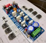
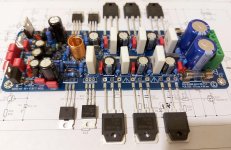
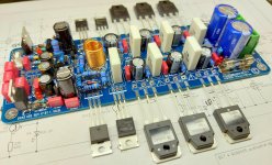
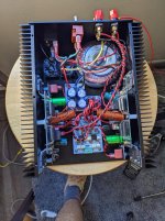
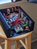
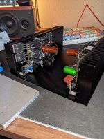
95% Power wiring has made 2.5mm2 fine silicone covered wire.
5% has made 2.5mm2 regular wire.
........
Great pictures thanks!
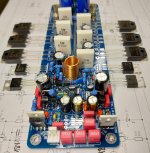
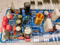
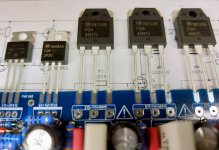
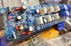
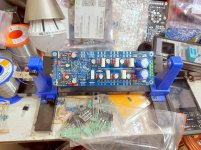
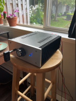
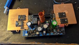
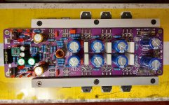
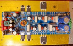
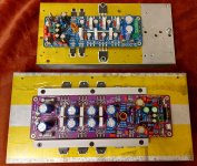
New Quad 405 Q17 by Tiberiu Vicol schematic, and PCB by me . 🙂
Rgards,
Alex
Rgards,
Alex
Attachments
-
 20210831_193050-001.jpg820.9 KB · Views: 1,403
 -
 20210831_192957-001.jpg684.2 KB · Views: 1,354
 -
 20210831_193101-001.jpg917.7 KB · Views: 1,329
 -
 20210831_193112-001.jpg808.7 KB · Views: 1,284
 -
 20210831_191140-001.jpg982 KB · Views: 1,220
 -
 20210831_193043-001.jpg1 MB · Views: 440
 -
 20210831_132334-001.jpg989.8 KB · Views: 464
 -
 20210831_132313-001.jpg1,008.3 KB · Views: 578


New Quad 405 Q17 by Tiberiu Vicol schematic, and PCB by me . 🙂
Rgards,
Alex
That is beautiful. I love the component choices!
Big thanks to Bonsai and jxdking for their assistance on my signal ground question thread.
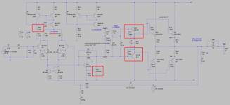
I'll start out with schematic:
- I believe this is just a basic blameless amplifier
- both channels biased for 20 mV across emitter resistors
- EF follower VAS
- easy peasy 100pF miller cap
- ran into stability issues
First issue:
- realized design was bad with main VAS TR as BC549C, too low Vce rating, rails are +/- 21 V (not rms) after transformer
- replaced with MPSA06
Second issue:
- after replacing with VAS TR to a MPSA06, right channel heatsink incredibly hot
- look at bias, 100 mV
- take amplifier out of chassis
- attach to external psu
- PSU starts to pull an amp from each rail when I probe base of MPSA06, the VAS TR
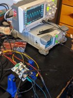
- after sitting on it for a few days, finally probe output with oscilloscope (should have done this earlier, duh)
- turns out there is an incredibly clean oscillation at 11 MHz
Fixing second issue:
- you can see pic where I reposted schematic with changes
- first change: lowering tail current in input stage, this brought phase margin back 20-40 degrees, at least in simulation, by itself didn't cure oscillation
- second change: added 100n caps across base emitter junction of driver TRs
- after second change oscillation completely went away
- can now probe base of MPSA06 and everything looks good
Anyways, that's the most interesting part of the journey, here are the pics.
I'll start out with schematic:
- I believe this is just a basic blameless amplifier
- both channels biased for 20 mV across emitter resistors
- EF follower VAS
- easy peasy 100pF miller cap
- ran into stability issues
First issue:
- realized design was bad with main VAS TR as BC549C, too low Vce rating, rails are +/- 21 V (not rms) after transformer
- replaced with MPSA06
Second issue:
- after replacing with VAS TR to a MPSA06, right channel heatsink incredibly hot
- look at bias, 100 mV
- take amplifier out of chassis
- attach to external psu
- PSU starts to pull an amp from each rail when I probe base of MPSA06, the VAS TR
- after sitting on it for a few days, finally probe output with oscilloscope (should have done this earlier, duh)
- turns out there is an incredibly clean oscillation at 11 MHz
Fixing second issue:
- you can see pic where I reposted schematic with changes
- first change: lowering tail current in input stage, this brought phase margin back 20-40 degrees, at least in simulation, by itself didn't cure oscillation
- second change: added 100n caps across base emitter junction of driver TRs
- after second change oscillation completely went away
- can now probe base of MPSA06 and everything looks good
Anyways, that's the most interesting part of the journey, here are the pics.
Attachments
-
 8 - front panel.png934.8 KB · Views: 631
 -
 7 - overhead view.jpg401.7 KB · Views: 657
 -
 6 - pre front panel and volume knob.jpg854 KB · Views: 596
 -
 5 - mock assembly.jpg873 KB · Views: 509
 -
 4 - heatsinks drilled and tapped.jpg705.7 KB · Views: 490
 -
 3 - prototype of preamp.jpg757.6 KB · Views: 461
 -
 2 - listening to both channels.jpg857.6 KB · Views: 495
 -
 1 - initial prototype.jpg899.1 KB · Views: 560
 -
 post oscillation mods.png251.6 KB · Views: 511
 -
 pre oscillation mods.PNG242.8 KB · Views: 644
Nice amplifier. Interesting fixes, but this isn't the place to share thoughts on them. I hope those capacitors on the output don't affect SQ much.
Ahh. As every design experience is a combination of things you got right and things you got wrong, I thought providing a small explanation or context of what that journey was like for me would be a nice addition. My apologies, I did not intend to pollute this thread with that type of discussion. If a moderator deems it inappropriate, please feel free to remove it. Thank you!Nice amplifier. Interesting fixes, but this isn't the place to share thoughts on them. I hope those capacitors on the output don't affect SQ much.
edit: I forgot to mention, it sounds great! 🙂
Sorry, not at all, I read every word. If you did have a thread on it, I would be keen on finding out more. I'm glad it sounds good!


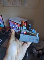
This is a very nice implementation manniraj. I like the VU meters that look vintage. I hope you will get rid of the hiss soon….
I suppose that you use slightly bigger speakers than the ones shown….😉
Fab
I suppose that you use slightly bigger speakers than the ones shown….😉
Fab
This is a very nice implementation manniraj. I like the VU meters that look vintage. I hope you will get rid of the hiss soon….
I suppose that you use slightly bigger speakers than the ones shown….😉
Fab
Thanks Fab, it seems that this amp has hiss issues even in the original design looking at the reviews. I think Nigel said the same in his PCB layout in the swap meet thread too. Need to see how is that implemented if at all like including a cap+resistor in the input signal side.
Manniraj,
Nice looking build!
The VU meters came with the chassis or you bought separately?
Fab,
Good catch on the speakers in Manniraj's pic - this would be a unique case of the the amplifier being several times larger in volume than the loudspeakers! 😀
Like you I am confident that Manniraj has bigger speakers... 🙂
Thanks zman01, the cabinet is made in India and the front panel is my imagination that one of my local friend was able to get into the design and CNC machined. I had these small sized VU meters so used in this cabinet.
Nice catch on the small satellite speakers and I forgot to see Fab's response on that too 🙂. They are the Energy satellite speakers from my old 5.1 HT and still going strong and good for my bedroom setup where the Maplin is being used currently.
My main speakers are Troels Gravesen TQWT MKII and that is being powered by J2 mono blocs currently.
Thanks
Maplin amp using Prasi layout and tightly matched laterals 1058/162. I do get some hiss kind of sound on the amp irrespective of the source and playback. Need to figure out how to get rid of the hiss.
Very nicely done!
I struggled with hiss in the past. There are a few things I do
- Ground current source diodes on the input via capacitors
- Use low noise transistors in the input and VAS stages
- Use higher-power rated metal film resistors (0.5W rather than 0.25W for example)
- Avoid unnecessary heat
- Use as low bias currents as possible in input and VAS
Thanks Mrcloc, I have used all genuine and high quality parts in my build. Matched original laterals 1058/162 along with Wima caps, KSC/KSA transistors and Nichicon electrolytes. Hopefully as you said I need to use the input signals being closer but that anyway I have used Belden cable for internal signal cabling which are fantastic in all my other amp builds. I haven't yet tested this amp with a proper preamp and I have 2 of them right now the Korg B1 and the USSPA. Will try and see if the preamp in the mix eliminates anything as right now using the Amazon Echodot as the source direct to the amp 😀
Pre-amp + DAC + HP amp
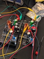
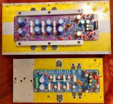
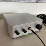
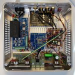
Here comes my little modular build.
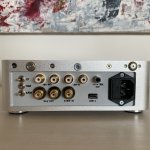
Pre-amp: Rod Elliott's P97 with tone controls, however skipped the balance regulator. It has two inputs - Line-in and DAC - toggled by the top button on the right side of the chassis and logic circuit with relay (the module on the right). The tone controls can be bypassed toggling the switch on the back driving another small relay.
DAC: Khadas ToneBoard, as is.
HP-amp: Neurochrome's HP-22. The module (in the center) looks strangely deserted but I just had to move most components elsewhere to accommodate all the ideas in the end. Hope TomChr does not mind🙂. I also added switchable gain (high/low) and cross-feed (modified schematic by Xen/Patrick from another thread) by two switches on the back + small relays.
PSU: again Neurochrome's ready module. The lower button on the right side of the chassis switches the whole thing on and off.
Here comes my little modular build.
Pre-amp: Rod Elliott's P97 with tone controls, however skipped the balance regulator. It has two inputs - Line-in and DAC - toggled by the top button on the right side of the chassis and logic circuit with relay (the module on the right). The tone controls can be bypassed toggling the switch on the back driving another small relay.
DAC: Khadas ToneBoard, as is.
HP-amp: Neurochrome's HP-22. The module (in the center) looks strangely deserted but I just had to move most components elsewhere to accommodate all the ideas in the end. Hope TomChr does not mind🙂. I also added switchable gain (high/low) and cross-feed (modified schematic by Xen/Patrick from another thread) by two switches on the back + small relays.
PSU: again Neurochrome's ready module. The lower button on the right side of the chassis switches the whole thing on and off.
Attachments

I hope you will get rid of the hiss soon….
Hiss does not bother me since I have chronic tinnitus. 😀 🙁
...since I have chronic tinnitus. 😀 🙁
...probably caused by enduring hiss. 😀
- Home
- Amplifiers
- Solid State
- Post your Solid State pics here