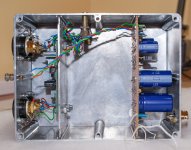

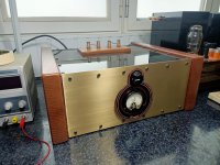
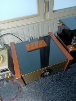
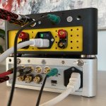
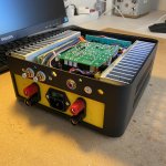
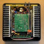
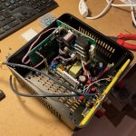
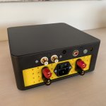
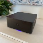
The audio multi-channel system that I made during the quarantine contains as following:
- 6 channels audio power amplifiers (250W ch/4 ohms (up to 3 channels driven) or 140W per ch/8hms for all channels driven) based on current dumping technique (from famous quad 405, actually a modified version including among the modifications usage of 4 transistors Sanken 2SC2922, OPA134)
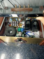
- supply with 1000VA torroidal transformer with inrush current limitation with fail-safe function, 84600uF total cap area per 50V rail with inrush current limitation for charging and supply ok detection such that when the capacitors are almost at 80% charge the relays are bypassing the current limiters (less stress on toroidal transformer)
- overtemperature protection per every channel with sensor mounted between the power transistors, dc component speaker protection, overcurrent limitation per every channel (but this I removed 🙂)
- the entire protection module is galvanically isolated with and independent supply and voltage monitoring is done with help of optocouplers stages
I am happy with the sound and overall performance.
Now THAT is an ampbuild by my taste. No waist of space. Love it.
Hi Paul
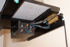
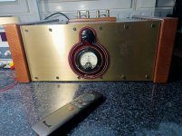
I got the vu meters fro jlmaudio. Unfortunately they are a real challenge to get working in my opinion. They are still not working consistently and I have now been advised it would be better to wire them to the outputs and not the inputs like I have...sigh...
When I get motivated I will pop it open and resolder to the outputs.
Regards
Richard
Hi doolybird,
I've started buying up parts for the Honey Badger Amp and was having trouble with finding a case for my project. Thanks for the info on the heatsinks, I'll give them a call tomorrow and organize pickup.
Where did you get the VU meters from?
Cheers
Paul
Now i have done it.
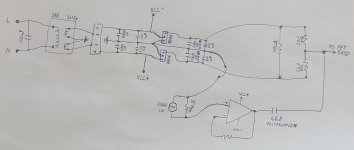
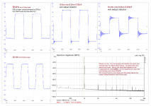
Somebody told me that buffer could be good idea before feed signal to my amplifier Gate pin.
So now i have made a new board to bias fet and there is a OpAmp to deliver the input audio signal with more power what the fets gate ever needs to maintain linearity every frequensy.
Picture maybe tell more then what i can write here.
I can tell that it was not easy task to make that board and keep the amplifier noise level down when there is not signal to present.
Finaly it get quite low noise when i made last change and that was separate main power cables somewhere else then side by side with signal and bias voltage cable.
I use microfone cable where outer shiel work as a ground and for that reason the connection with the dother board and the mains ground pin are together close to fet pin instead the star ground what everything else use.
Attachments
Last edited:
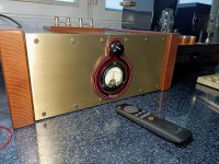
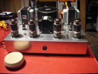
Hiraga Le Monstre
My Hiraga 8W
My Hiraga 8W
Attachments


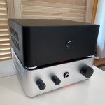
ESP P101
Hi there,
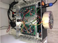
this is my little companion to the pre-amp I built before. It is the low power version of P101 – breathes from 38V rails by SMPS. 50mA bias. Ran through lots of simulations and adjustments of operating conditions to squeeze out max performance from this seemingly simple circuit. No idea whether my mods really make the amp sound better than the original, didn't build the base case configuration, but that was not the point - I am just a curious constructor. All in all, I think the performance vs. complexity of Rod Elliott's design is just outstanding! My most objective judgement – the amp is hard to switch off!🙂
Hi there,
this is my little companion to the pre-amp I built before. It is the low power version of P101 – breathes from 38V rails by SMPS. 50mA bias. Ran through lots of simulations and adjustments of operating conditions to squeeze out max performance from this seemingly simple circuit. No idea whether my mods really make the amp sound better than the original, didn't build the base case configuration, but that was not the point - I am just a curious constructor. All in all, I think the performance vs. complexity of Rod Elliott's design is just outstanding! My most objective judgement – the amp is hard to switch off!🙂
Attachments

- Home
- Amplifiers
- Solid State
- Post your Solid State pics here