Interesting circuit.
All Quasi-comp-Amps i saw before, were built with NPN output Transistors.
I just like PNP. There is no technical reason to choose them...🙄
I use quasi complementary design because I don’t think I could find matching output transistors.
What do you use the J4 connector for?
See that I already bridged C16. If you put J4, there is no more Cap (C9 C10) outside of the closed loop. Pure sound. I believe C9 is not a very good place for an unipolar electrolytic.... also, some tests with awful caps gave me bad results, they cut negative voltages.
My tests on regulated power supply resulted that the cap C9 is not needed, the DC offset is same with or without it, around 10mV. I still have to repeat this same test for the unregulated supply - by using J4.
Interesting circuit.
And the double-differential design is well explained in the book of Douglas Self (the free online version).
Actually “my” only contribution is the NTC bias regulator with the BAT43, but there is high risk I reinvented the wheel
 again 😱
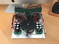
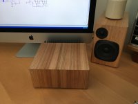
Just finished the amp for my computer speakers. Four 50W lateral mosfet monoblocks (aem6000 derived design), with two-way active crossovers. The two sides (woofer + tweeter) have independent rectifiers and filtering, but share a single transformer. The whole lot sits in a 20 x 20 x 9 box, made from aluminium and tassie Oak.
On the filter boards there’s a dc protect and anti-thump circuit. In use it tucks discretely behind my Mac, plugged into the headphone socket.
On the filter boards there’s a dc protect and anti-thump circuit. In use it tucks discretely behind my Mac, plugged into the headphone socket.
Attachments
Hi Suzy,
Clean build for something so compact. Well done - as usual!
You know what they say about a clean desk or work bench don't you? 😀
Is that an HP 3585 on your bench? Nice instrument, I use one as well.
-Chris
Clean build for something so compact. Well done - as usual!
You know what they say about a clean desk or work bench don't you? 😀
Is that an HP 3585 on your bench? Nice instrument, I use one as well.
-Chris
Very nice! Cool build.
Just finished the amp for my computer speakers. Four 50W lateral mosfet monoblocks (aem6000 derived design), with two-way active crossovers. The two sides (woofer + tweeter) have independent rectifiers and filtering, but share a single transformer. The whole lot sits in a 20 x 20 x 9 box, made from aluminium and tassie Oak.
On the filter boards there’s a dc protect and anti-thump circuit. In use it tucks discretely behind my Mac, plugged into the headphone socket.
Hi Suzy,
Clean build for something so compact. Well done - as usual!
You know what they say about a clean desk or work bench don't you? 😀
Is that an HP 3585 on your bench? Nice instrument, I use one as well.
-Chris
Don’t worry - the rest of the desk is a shambles. It is indeed a 3585b. Bloody lovely spectrum analyser, though I’ve gotta have a bit of a play with it as it keeps losing lock.
Suzyj,
A compact and pretty looking amp you got there. It matches nicely with the speakers too. Well done!
A compact and pretty looking amp you got there. It matches nicely with the speakers too. Well done!
Hi Suzy,
Mine is a 3585A, not sure what the differences are. I have no doubt it is an upgraded 3585A!
I have what is called a "T-Bolt" GPS disciplined 10 MHz oscillator and an HP 5087A distribution amplifier. The frequency reference gives you an instant upgrade for frequency. Yours might have a sick oscillator if you have the high stability timebase option (mine does). I have also locked the HP 3325A and a few other pieces to the same frequency. It's nice to output a frequency off one piece of gear and have it measure the exact same on another! This bit of kit should run somewhere in the $150 ~ $200 range in Canadian dollars. The antenna is another $20. You can use other brands, just make sure it is a timing GPS and not a position type. You want a 10 MHz output too.
Best, Chris
Mine is a 3585A, not sure what the differences are. I have no doubt it is an upgraded 3585A!
With the frequency reference?I’ve gotta have a bit of a play with it as it keeps losing lock.
I have what is called a "T-Bolt" GPS disciplined 10 MHz oscillator and an HP 5087A distribution amplifier. The frequency reference gives you an instant upgrade for frequency. Yours might have a sick oscillator if you have the high stability timebase option (mine does). I have also locked the HP 3325A and a few other pieces to the same frequency. It's nice to output a frequency off one piece of gear and have it measure the exact same on another! This bit of kit should run somewhere in the $150 ~ $200 range in Canadian dollars. The antenna is another $20. You can use other brands, just make sure it is a timing GPS and not a position type. You want a 10 MHz output too.
Ahhh! My faith in you has been restored! 🙂Don’t worry - the rest of the desk is a shambles.
Best, Chris
Good question! The error that comes up is simply “lost frequency lock”, accompanied with a drop-off in amplitude. It’s got a high-stability ocxo, and I don’t generally connect it to an external reference. Indeed if I need an accurate reference this is generally the one I use as source.
I’m guessing it’s synth is crook and dropping out of lock with it’s own reference. Alas it’s an error that I can generally clear by driving the rbw up a step and then back down, so whatever it is it’s marginal which means I haven’t bothered to fix it yet. Thankfully I have the full service documentation for the machine.
I’m guessing it’s synth is crook and dropping out of lock with it’s own reference. Alas it’s an error that I can generally clear by driving the rbw up a step and then back down, so whatever it is it’s marginal which means I haven’t bothered to fix it yet. Thankfully I have the full service documentation for the machine.
Hi Suzy,
Well, its bothersome enough to mention, and I can see you fighting with your equipment (never the way to work).
I should have said that the "T" in "T-Bolt" is Trimble. Many of these hit the surplus market a few years ago. One extremely valuable resource for you would be the "Time Nuts" group. The members have very technical web sites and also support test instrumentation. Let's see here ... American Febo Enterprises . This can get as involved as you want with regard to accuracy timing / frequency control. We are talking 10 exp -12 area errors. Substantially better than the high accuracy frequency reference in your 3585B which would be on the order of 10 exp -9 just after calibration. This reference is locked to the GPS constellation, so your accuracy is always being corrected. For doing critical measurements it isn't uncommon to put the reference into "holdover" mode so it doesn't do a step correction during your measurement / experiment.
From what little I know of you, you might find this fascinating. Enough to make a small expenditure that would allow you to eliminate frequency drift in all of your equipment.
I guess I should turn this thread back over to people building stuff and showing it off! You can PM me if you have any questions.
Best, Chris
<grin> I look after a maser and a couple of GPS disciplined rubidiums at work, so have access to some fairly accurate timing.
I have zero (to an accuracy of at least 10^-15) interest in replicating any of that at home!
I have zero (to an accuracy of at least 10^-15) interest in replicating any of that at home!
Last edited:
Hi Suzi,
Now there is an accurate timing source!
No, I was thinking of just a simple xtal oscillator disciplined to the GPS network. A few orders of magnitude worse than your gear at work. Something simple that you can connect and forget about! No backup sources required either.
What do you use to distribute the reference frequency? I should say that I'm very jealous of your access to a great timing setup. I'm struggling to keep mine running well, never mind trying to create a distribution amplifier with isolated outputs. My guess is that you have forgotten more than I know about precision timing!
Anyway, the option for a precision oscillator in most test equipment is so much more costly than a single frequency reference and distribution amplifier (some folks use a video distribution amplifier) that going that route makes financial sense. In my own work, having the equipment locked to a single reference really makes a huge difference, and I don't have to calibrate the oscillators any more. Even the cost to calibrate one reference oscillator can exceed the cost of a complete GPS reference solution!
You know, one thing that really bothers me is that all the equipment pulled from cell towers when they refresh the electronics is not available to purchase. In fact, it is a big secret as to what is done with the equipment. It could help so many home labs.
Best, Chris
It’s moderately complicated, and mostly done with in-house gear. The first problem is that we have (quick mental arithmetic) ~800 odd chassis that each need time, and they’re distributed across a fairly big room. Next is that we use 16MHz, not 10MHz, as our standard, because it divides cleanly to 1. So we start by driving a low noise PLOCXO with each of the 10MHz references to get 16. That and 1pps go into a board that generates a binary atomic time (BAT) signal that encodes UTC into the 1pps. The distribution is done with a mix of single-mode fibre using passive splitters driven by networking optical transceivers at the timing rack, and then a pair of further optical receivers and 12 way active electronic splitters at each destination rack.
We have some coax 10MHz distribution as well, for collaborators and other uses. We just use PTF distribution amps (from memory 1203C | Precise Time and Frequency, Inc) for that.
We have some coax 10MHz distribution as well, for collaborators and other uses. We just use PTF distribution amps (from memory 1203C | Precise Time and Frequency, Inc) for that.
Last edited:
Hi Suzy,
Thank you very much for the link. I have something to explore now. 🙂
Okay, so at work you have had way more fun than should be allowed when you're getting paid for it! I am impressed, but also a little confused. The optical distribution makes a lot of sense, and buys you the isolation needed to avoid ground loops. What I am trying to understand is why you went with a 16 MHz signal in order to generate the 1 pps signal that most timing and location GPS units output anyway? I am well aware that you'll have a very good reason for it. I just can't think of it off-hand. There are many DIY oscillator control boards designed that use the 1 pps signal to generate and discipline normal ovenized 10 MHz oscillators out there. That would cover your internal needs (and also that of many outside requirements). The 10 MHz output would then feed whatever outside needs you might run into.
At any rate, Suzy, I am very impressed with your involvement in an ultimate DIY project! I am well aware of how much trouble you must have gone through to keep jitter and mains effects out of your timing network. That and to embed time code into your 1 pps signal isn't really a trivial task. My hat comes off for you!
Best, Chris
Like any big project, there’s a large group of people doing the design work. I’m just one person in a long chain, mainly responsible these days for install & maintenance. It’s also built on stuff that goes back decades in development, used in various telescopes.
I probably didnt explain the 16MHz terribly clearly. Our samplers can be configured to run at 1280 or 1536 MHz to cover our RF band in three nyquist zones. The samplers also have a filter bank to channelise the data into 1MHz channels. All this works well with integer synthesisers with a 16 MHz reference. If we distributed 10 we’d have to use more complicated synthesisers at the samplers, with a penalty in phase noise and spurs.
Like any job there’s moments of joy, moments of frustration and a lot of work, plus way too many emails and meetings 🙂 It is cool to see the fruits of our labour though.
Hi Suzy,
All that makes good sense. I'll agree with you on the meetings and emails. I had someone retire me, but I still end up dealing with those things. Except now I'm not compensated for the work.
Well, you should be proud of your part in all that. Do you get points for biting your tongue?
-Chris
All that makes good sense. I'll agree with you on the meetings and emails. I had someone retire me, but I still end up dealing with those things. Except now I'm not compensated for the work.
Well, you should be proud of your part in all that. Do you get points for biting your tongue?
-Chris
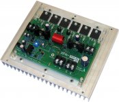
THD+N is about 0.0008% @ 150 watts/4 ohms.
Hi George
yeah great build.
Definetly better heatsinked than my build in post #5390 🙄
Want to post schematics?
Please tell me, how you measure a THD when it is so small. Do you have dedicated circuitry, equipment,...?
The THD was measured with a spectrum analysis of the residual from the output of an HP339A which is an incredible instrument for it's time. The noise component is then added to the sum of the harmonics. I should have mentioned in the original post that this was the 1khz measurement. The 10khz isn't much worse at about 0.0012%. There is definitely no audible distortion and the crossover is incredibly low. The heatsink pictured is for versions that don't use fans and incredibly it will put out 80 watts continuous sine wave! Many Hi Fi amps will go up in smoke with that sort of abuse. The tripple paralleled outputs both lower crossover distortion and give it a good 10x margin on heat dissipation. I think that I can release the schematic (pretty conventional actually), but I will get permission anyway as this is a commercial product now as an industrial module (integrated PA systems etc.).
- Home
- Amplifiers
- Solid State
- Post your Solid State pics here