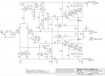
I think that I can release the schematic (pretty conventional actually), but I will get permission anyway ...
Agree, no need to bother, pretty conventional, so trivial one can clearly read SCH from PCB. Amps should not be motor drivers only, so W, A, MHz, ... are basics and have pretty little in common with sound quality. Great work though.
I should have mentioned in the original post that this was the 1khz measurement. The 10khz isn't much worse at about 0.0012%.
Way cool. The 10KHz result is indicative of plenty of bandwidth and fast slew rate. Looks beautiful, too.
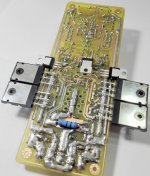
Indeed that is a binder (bulldog) clip on the input and current mirror transistors which simply helps to keep them close to the same temperature. The output DC of this amp rarely goes beyond +/-1 mV and I have never had one worse than +/-2 mV. The transistors are not matched beyond simply taking them from the same strip. I just cut them off in pairs and the Vbe matches close enough. For some critical (non audio) applications I have sorted from there, but not for production units.
Thanks SuzyJ, I think it's cool too 🙂 It has a pretty symmetrical 40V/mS slew rate and has no trouble being perfectly flat and effectively distortionless well into the ultrasound.
Although this amplifier is primarily used for PA and Hi Fi applicaions, I have techniques that put tube/valve style distortion into it for guitar applications. I have other designs that do this in my production guitar amps. Audio circuits are no doubt a source of infinite fun.
Although this amplifier is primarily used for PA and Hi Fi applicaions, I have techniques that put tube/valve style distortion into it for guitar applications. I have other designs that do this in my production guitar amps. Audio circuits are no doubt a source of infinite fun.
so trivial one can clearly read SCH from PCB.
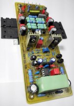
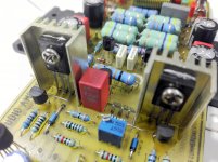
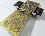
Unfortunately, I can't 😕 There are 2 driver transistors on the left and only one on the right 😕 Some loose transistors spread around the PCB with the routes being below. How is thermal runaway considered, only the output transistors seem connected to the heatsink 😕 Anyhow this thing took 4 years to build as I see, with the use of pro equipment. I'd be very happy for a schematic (even w/o values if you want to keep those) or a similar reference. Thanks.
How is thermal runaway considered, only the output transistors seem connected to the heatsink 😕
CFP output. The thermal compensation is on the left driver.
Sajti
My lastest idea to ''end of the story'' amplifier is very close 😀
In the nature bird is flying, fish is swimming, vacuum tube is amplifying voltage and BJT's are amplifying current.
So why not to let it stay this way ? In my opinion perfect combo.
Some 40-60hours more of work, slowly but forward 😀
Regards
In the nature bird is flying, fish is swimming, vacuum tube is amplifying voltage and BJT's are amplifying current.
So why not to let it stay this way ? In my opinion perfect combo.
Some 40-60hours more of work, slowly but forward 😀
Regards
Attachments

Nice Peter!!!My lastest idea to ''end of the story'' amplifier is very close 😀
In the nature bird is flying, fish is swimming, vacuum tube is amplifying voltage and BJT's are amplifying current.
So why not to let it stay this way ? In my opinion perfect combo.
Some 40-60hours more of work, slowly but forward 😀
Regards
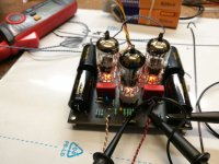
Is power amplifier the i=AMP100?
I see an input stage together,what is the role of tubes,is it a buffer?
Last edited:
thimios
Yes the OPS is standard EF2 i100 with some sanken outputs. Very simple input stage has only x2 of voltage gain, so it takes approx 40V of the amplitude at the input.
The tube preamp has voltage gain of x20 so the total amplifier gain is aprox x40.
Solid state amplifier works more like a current buffer for the tube stage.
The general idea is to clone the most of the ''tube sound'' to the solid state output stage, it can not be done in tube-LTP-way as I was doing it before.
I have some plan B too but it will be a bit complicated so have to prepare 2-3 prototypes.
Regards
Attachments
Thanks Peter.thimios
Yes the OPS is standard EF2 i100 with some sanken outputs. Very simple input stage has only x2 of voltage gain, so it takes approx 40V of the amplitude at the input.
The tube preamp has voltage gain of x20 so the total amplifier gain is aprox x40.
Solid state amplifier works more like a current buffer for the tube stage.
The general idea is to clone the most of the ''tube sound'' to the solid state output stage, it can not be done in tube-LTP-way as I was doing it before.
I have some plan B too but it will be a bit complicated so have to prepare 2-3 prototypes.
Regards
You have done a long travel to the tube world 😉
Good luck.🙂
Yes it is a CFP output. In my experience building audio amps I have never actually seen thermal runaway in practice. The thermal compensation is primarily for maintaining accurate bias to minimize crossover distortion.
well ...i think that you might have done a very nice simulation but i think that this amplifier in real life will eventually fail ....I think that your cfp reading is poor ....I think that also your choice of semis is even more poor But still the worst think to do is think EFP and construct CFP with the wrong semis ....
There is other more details that are wrong to my opinion but of less importance ...
Just my opinion...no hard feelings here time will tell ....
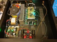
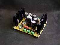
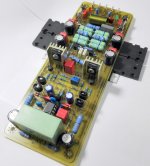
HPA 150 audio amplifier build in progress 🙂
Attachments
-
 IMG_20171116_171922.jpg473.9 KB · Views: 1,097
 -
 IMG_20171116_171934.jpg465.6 KB · Views: 1,073
 -
 IMG_20171116_171945.jpg942.7 KB · Views: 1,027
 -
 IMG_20171116_171950.jpg979.3 KB · Views: 965
 -
 IMG_20171116_172002.jpg980 KB · Views: 906
 -
 IMG_20171116_172014.jpg532 KB · Views: 239
 -
 IMG_20171116_172157.jpg824.3 KB · Views: 272
 -
 IMG_20171116_172204.jpg548.8 KB · Views: 305
 -
 IMG_20171116_172215.jpg801.4 KB · Views: 313
 -
 IMG_20171116_172223.jpg659.4 KB · Views: 404
Beautiful!HPA 150 audio amplifier build in progress 🙂
I know the pcb designer but what is the schematic?😉
Interesting thimios, but this is not a simulation. The XPA-150 has been a production product since 2013 and the first version was released in 1996. If it were so wayward, I would be hearing about it by now. 🙂
Member
Joined 2009
Paid Member
George, I think you got your Greeks mixed up, it wasn't Thimios pouring cold water on your project. But East Electronics has a lot of experience with many kinds of amplifiers and their reliability.
FWIW, I like CFP outputs driven by compound VAS too.
FWIW, I like CFP outputs driven by compound VAS too.
Last edited:
Thanks Bigun, Indeed I did get my Greeks mixed up. Sorry Thimios. It really wasn't cold water really anyway, just observations and opinions etc. I am just pointing out that this is a very tried and true design that is in production and in service. It is not experimental and performs incredibly well. And I am interested in and waiting for details regarding these opinions.
Attachments
Last edited:
- Home
- Amplifiers
- Solid State
- Post your Solid State pics here