Hi mosquito,
The 4570 isn't a bad op amp at all. Its better than what you normally find in a Japanese phono preamp circuit. I like your re purposing of the tape head preamp circuit. Its surprising to see that was used in portable equipment. Have you checked the feedback network, or changed it to RIAA? The tape EQ curve is very broadly similar to a phono EQ.
-Chris
Hi anatech, yes the circuit was modified, to accomplish the true RIAA eq. Though nothing split RIAA, nor passive eq, just the basic active "all in once" circuit. Practical, quick and dirty, zero cost, but it does the duty very well.
Hi mosquito,
Perfect.
BTW, there is nothing wrong with "all at once" circuits. The few improvements to what you have done here are not compatible with the spirit of your project.
What are they? Probably PCB layout and power supply. Lowering the impedance of that feedback network to improve noise and adding a buffer on the op amp output to drive that lower impedance feedback network. Then, some parts could be improved. You can see by all this that what you have done is great, just as it is right now.
I wish more folks would simply build things and try them. Your effort was nicely executed and stands for itself just fine!
-Chris
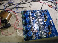
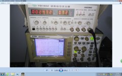
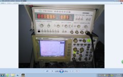
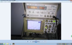
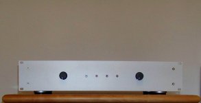
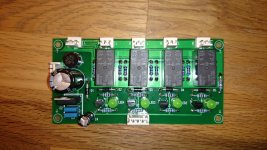
MY NEW HIFI PREAMP, I THINK TI IS VERY GOOD ONE!😀
Attachments
-
 QQ??20150515224302.jpg187 KB · Views: 1,113
 -
 QQ??20150515224218.jpg242.5 KB · Views: 590
 -
 QQ??20150515224226.jpg111.5 KB · Views: 260
 -
 QQ??20150515224237.jpg189.2 KB · Views: 126
 -
 QQ??20150515224241.jpg189.9 KB · Views: 130
 -
 QQ??20150515224246.jpg200.2 KB · Views: 943
 -
 QQ??20150515224249.jpg165.9 KB · Views: 986
 -
 QQ??20150515224254.jpg184.6 KB · Views: 1,022
 -
 QQ??20150515224257.jpg190.9 KB · Views: 1,074
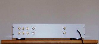
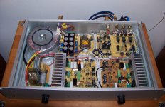
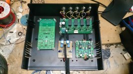
Hi 2011diy,
Yes, your build looks professional, as if it is for sale as a product.
I am have missed this, but what design are you using? Can you post the diagram and tell us about it? Maybe some members would like to build something similar to yours. I would have to say that this build is of very high quality. Please tell us about it.
-Chris
"Basic EF" (Pro 60) stereo amp by G.Randy Slone
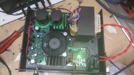
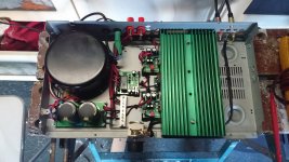
Hi folks,
let me show you a good working SS design that sounds great
in comparison to what I've owned before. With some help from
my friend, I've added an electronic source selector, a relayed
on/off switch and a short circuit/dc protection with a turn ON
delay circuit (Slone).
The left knob is an ALPS 3 in 1 device from a car radio that I use
only for two functions, turn on/off and source selector. The right
knob is an ordinary BOURNS log potentiometer. All the parts are
hard wired because I didn't want to mess around with chemicals
and stuff. The enclosure is a Fischer Elektronik.
Took me about 80 hours to assemble the whole amp.This particular
design (not the amp itself) has served me for the last 12 years and it
didn't break, so I guess I can recommend it. In case anyone wants
to know, the schematic is on figure 6.2 page 137 of the "The Audiophile's
Project Sourcebook" by G.Randy Slone. I haven't included any markings
on the device for this is only for those who know what this is and how
to use it. 😉
Attachments
There is not much to see except solid wire routed exactly
as the pcb traces show. Imagine a transparent foil of it
attached with 2 sided scotch tape on the board and the wires
go on top of it. I did that for the upper side of the board too
so it's easier to place the parts in right place.
as the pcb traces show. Imagine a transparent foil of it
attached with 2 sided scotch tape on the board and the wires
go on top of it. I did that for the upper side of the board too
so it's easier to place the parts in right place.
I'd love to see under all that perfboard...
I don't recall ever to have seen silk-screened perfboard.
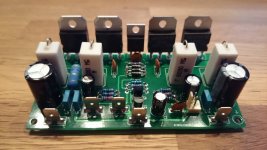
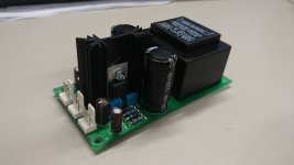
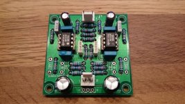
Sub Sat preamp/filter/amps
The last year or so I have designed several PCBs that make a complete set of modules for a Sub/Sat system.
I'm working on the following modules:
- Preamp with relais input switching and MM preamp
- Sub/Sat filter with adjustable subsonic filter, lowpass, highpass, adjustable boost, phase switch
- Mono amp for subwoofer
- Stereo amps (LM1875 based and LM3886 based)
Attachments
-
 sub_sat_1.JPG78.9 KB · Views: 414
 -
 sub_sat.JPG133.5 KB · Views: 478
 -
 sub_amp_1.JPG161 KB · Views: 535
 -
 sub_amp.jpg119.9 KB · Views: 1,093
 -
 pre_supply.JPG83.7 KB · Views: 1,074
 -
 phono.JPG206.2 KB · Views: 1,225
 -
 input.JPG181.8 KB · Views: 1,278
 -
 preamp.JPG188.2 KB · Views: 1,330
 -
 DSC_0521.jpg199.3 KB · Views: 510
Looks impressive seven.The last year or so I have designed several PCBs that make a complete set of modules for a Sub/Sat system.
I'm working on the following modules:
- Preamp with relais input switching and MM preamp
- Sub/Sat filter with adjustable subsonic filter, lowpass, highpass, adjustable boost, phase switch
- Mono amp for subwoofer
- Stereo amps (LM1875 based and LM3886 based)
"The Albert"
Let me introduce you to The Albert it has taken nearly 3 years to complete but here it is for all to see.


View attachment The Albert.pdf
Let me introduce you to The Albert it has taken nearly 3 years to complete but here it is for all to see.
View attachment The Albert.pdf
"The Albert"
Let me introduce you to The Albert it has taken nearly 3 years to complete but here it is for all to see.
View attachment 484717
View attachment 484718
View attachment 484719
Nixies!!!! I love Nixie Tubes! Is that a magic eye indicator thingy? Details!!!
I'm glad you love Nixies cause I do!
The Dekatron is an earlier version of the Nixie, information on it follow this link in fact this is where I learned how to drive them together with circuit diagrams. I use the Dekatron as a means of telling me what program position I'm at. I have 5 inputs and since it has 30 elements in it anywhere in a group of 6 is shown.
https://threeneurons.wordpress.com/dekatron-stuff/auxiliary-dekatron-stuff/
The Magic eye is a completely different animal in fact is has a heater just like a normal tube and is driven by an analogue voltage to indicate signal strength.
My next amp will be as I said based upon the F6 and it will have a couple of Dekatrons doing the same thing as the magic eye but I need to learn how to program an arduino chip first. The Dekatrons I will be using for that are rare purple in colour!
I tried to make a gif from a video I shot of The Albert you can see it here it is a lot smoother than that in real life. In fact I'll try another go at posting it on Youtube.
Albert on Make A Gif
Love the nixie's"The Albert"
Let me introduce you to The Albert it has taken nearly 3 years to complete but here it is for all to see.
View attachment 484717
View attachment 484718
View attachment 484719

The last year or so I have designed several PCBs that make a complete set of modules for a Sub/Sat system.
I'm working on the following modules:
- Preamp with relais input switching and MM preamp
- Sub/Sat filter with adjustable subsonic filter, lowpass, highpass, adjustable boost, phase switch
- Mono amp for subwoofer
- Stereo amps (LM1875 based and LM3886 based)
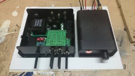
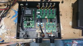
I have finished the preamp. Think I will design a small PCB for the line stage as well, then there is no perf board inside anymore.
Just one question. What would be the best place to connect the earth connection for the turntable input?
To the Phone preamp board, or directtly to the powersupplY?
Thanks in advance.
Attachments
Last edited:
I have finished the preamp. Think I will design a small PCB for the line stage as well, then there is no perf board inside anymore.
Just one question. What would be the best place to connect the earth connection for the turntable input?
To the Phone preamp board, or directtly to the powersupplY?
Thanks in advance.
I would suggest the case / enclosure earth directly. In your pic I dont see an earth wire from the wall socket connected to the case.....then use the power supply 0V. But I would suggest connecting the case directly to earth.
Last edited:
- Home
- Amplifiers
- Solid State
- Post your Solid State pics here