As I've learned recently, buying an smps psu for audio use is quite a crap shoot. The specs are almost useless; units with the same noise spec have noise concentrated in different parts of the spectrum, even though most have switching frequencies in the 40kHz to 100kHz range.
I think the most useful thing we can do to take some of the uncertainty out of it is to document their noise performance.
So when you get a new model of switcher, or have an interesting older one, do a noise curve measurement and post it. That way we can all avoid the lemons.
I suggest these parameters for the test.
: MAKE SURE you AC COUPLE the input to your analyzer !! Bad things will likely happen if you don't.
: A frequency range from somewhere near the mains frequency to ~ 100kHz, so the switching freq is captured.. Higher is ok too.
: A few averages will smooth the data for better presentation.
: Measure with the output loaded to deliver a supply-appropriate amperage, say 1/3 to 1/2 its rated amperage.
: Specify whether the supply output is earthed or not. Some smps will squeal when earthed.
Any other suggestions welcome.
------------------------------------------
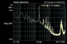
I'll start by posting one to avoid, the turkey that prompted this inquiry for me. An XP Power LCS50US15, rated 15V @ 3.4A. This thing stinks for audio, the largest noise spike is at 1.7kHz (and its harmonics). And this measurement was with 1,000uF on its output. Stock, it's even worse. I had to float the analyzer input, it does not like its output earthed.
I think the most useful thing we can do to take some of the uncertainty out of it is to document their noise performance.
So when you get a new model of switcher, or have an interesting older one, do a noise curve measurement and post it. That way we can all avoid the lemons.
I suggest these parameters for the test.
: MAKE SURE you AC COUPLE the input to your analyzer !! Bad things will likely happen if you don't.
: A frequency range from somewhere near the mains frequency to ~ 100kHz, so the switching freq is captured.. Higher is ok too.
: A few averages will smooth the data for better presentation.
: Measure with the output loaded to deliver a supply-appropriate amperage, say 1/3 to 1/2 its rated amperage.
: Specify whether the supply output is earthed or not. Some smps will squeal when earthed.
Any other suggestions welcome.
------------------------------------------
I'll start by posting one to avoid, the turkey that prompted this inquiry for me. An XP Power LCS50US15, rated 15V @ 3.4A. This thing stinks for audio, the largest noise spike is at 1.7kHz (and its harmonics). And this measurement was with 1,000uF on its output. Stock, it's even worse. I had to float the analyzer input, it does not like its output earthed.
Attachments
Last edited:

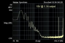
For context, here are a couple oldies that perform pretty well. Both were earthed.
An open-frame Boschert SL30-3612R industrial switcher from the mid-late 80's. Output variable from 10-24V at 5 Amps. I've used these for numerous things on the bench for quite a while. Not excellent, but good enuf.
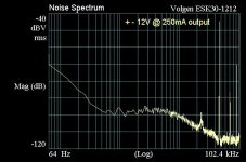
And a Volgen ESK30-1212 from the 90's. + and - 12V @ 500mA, and 5V @ 2.5A. I've used the bipolar 12V outputs for raw DC to a DAC with good results. Noise curve is excellent in the audio range.
An open-frame Boschert SL30-3612R industrial switcher from the mid-late 80's. Output variable from 10-24V at 5 Amps. I've used these for numerous things on the bench for quite a while. Not excellent, but good enuf.
And a Volgen ESK30-1212 from the 90's. + and - 12V @ 500mA, and 5V @ 2.5A. I've used the bipolar 12V outputs for raw DC to a DAC with good results. Noise curve is excellent in the audio range.
Attachments
Last edited:
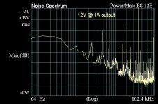
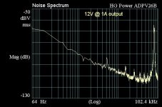
Here are a couple 12 volters. Both were earthed.
I have used the Power/Mate ES-12E 12V @ 5A to supply raw DC to a Stax headphone amp for the last year. It is worlds better tnam the linear wallwart that Stax supplied. Had I checked the noise output I might have looked further.
Such as this 12V 2-blade wallwart plugin. An HG Power ADPV26B, rated 12V @ 2 Amps. Really clean output, 80kHz switching frequency. A medical supply house was blowing these out for a buck a piece on eBay a couple years ago and I bought a bunch of 'em. This is now supplying the raw 12V to the Stax SRM-252S amp.
Attachments
Last edited:
I had been using my own designed SMPS in my system. No measurements of such kind because I lack of those instruments. But I sincerely didn't had any trouble during the 25 years of regular use diarily.
It is a one MOSFET switching FlyBack topology current mode using UC3842 as controller. MOSFET is a 7N60 both from STM and are re-used. Voltage control is TL431 and photocoupler PC817. It includes double line filter on board (2 x 2 x 36mH common mode chokes) plus 1uF X type and 0.01uF Y2. There is another built in the mains socket. The rectifiers are BYT13 1000 and is a 0.001uF parallel to each one. The drain of the MOSFET has a VK200 choke. The heat sink returns to high side negative. There is also a .01uF Y2 from negative to ground to close RF parasitics through trafo capacitance. Post rectification there is a 47uF 400V, a 150uH and 330uF more. All those elements provide from scrapped PC monitors including heat sinks, capacitors, active elements and chokes. Only new is the PC817 and the PCB. Snubber ate a 0.01uF parallel to 20K and diode is BYT01 1000.
At the secondary, 3 BYW98 200 gives me +/- 14V for TDA2030 and 12V for TDA2003 (3 each). Input filter capacitance is 3900uF, a 1uH small choke and 2200uF more. A second post regulator around L4794 from 12V to get 5.1V for logic. As it is a specific design, I took very care about layout of the PCB and filtering.
I have the schematic if any is interested in.
Attachments

For context, here are a couple oldies that perform pretty well. Both were earthed.
An open-frame Boschert SL30-3612R industrial switcher from the mid-late 80's. Output variable from 10-24V at 5 Amps. I've used these for numerous things on the bench for quite a while. Not excellent, but good enuf.
And a Volgen ESK30-1212 from the 90's. + and - 12V @ 500mA, and 5V @ 2.5A. I've used the bipolar 12V outputs for raw DC to a DAC with good results. Noise curve is excellent in the audio range.
Thanks for sharing!!
That Volgen looks pretty good. I checked the price - around $600-700 (!). I can build a high-quality liner power supply unit for that money (with a total of 4 very low noise small-signal transistors & 2 paralleled TO3 pass transistors).... single rail, around 6-7A constant current delivery. That includes high-quality capacitors as well. Sounds amazing.
It would be interesting to see how the latest runofthemill MeanWell's perform... I tried a 15V / 10A open-frame one... did a few tiny modifications and got it to sound very nice. I did not check it with (what I have at hand right now) my oscilloscope, though. But, for around $60-70 (some extra parts included...) it did sound very good.
The only thing I did not like about MeanWell SMPS is the change in operating frequency, which was load dependent. This was actually changing the sound character a lot, depending on which music player I was using (depending on the CPU current draw):
- one sound character for a low NUC11 CPU utilisation, with JRiver (similar sound signature as with my liner power supplies)
- completely different sound signature with HQ Player Pro and CPU utilisation close to 80-90% (x256DSD modulator: ASDM7ECv2 and poly-sinc long lp filter), compared to my liner power supplies.
If possible, measure the AUDIO band noise as well, before (presumably linear supply) and after with SMPS. The "conventional wisdom" is that switch mode supplies will make your audio dirty, but at least one fellow in some thread at Audio Science Review found that removing the large transformer dramatically REDUCED noise particularly from mains hum (USA 60 Hz and multiples).Any other suggestions welcome.
Nothing unusual, it's just a basic 100kHz FFT setup, AC coupled input, 250mV input range to be safe. Connected to the smps output with a Tek 1x probe which has ~ 200 Ohms series R, again to be safe. I'm pretty sure any recent sound card would work fine as long as it's AC coupled. Even a DSO with FTT and averaging might do. 10 bits with averaging will typically yield near 80dB dynamic range.
Last edited:
Agreed. Good topic and the information should be interesting and useful - but useless without a detailed description of the test setup.You should perhaps describe your measurement setup?
//
Hal
Nothing unusual, it's just a basic 100kHz FFT setup, AC coupled input, 250mV input range to be safe. Connected to the smps output with a Tek 1x probe which has ~ 200 Ohms series R, again to be safe. I'm pretty sure any recent sound card would work fine as long as it's AC coupled. Even a DSO with FTT and averaging might do. 10 bits with averaging will typically yield near 80dB dynamic range.
BTW, the XP Power unit above had 1,000uF on its output in the above measurement. Without it, its even worse.
The PS should have a load, preferably close to it's designed use current.
I assume you read the OP?The PS should have a load, preferably close to it's designed use current.
Yes... and completely overlooked that was mentioned.I assume you read the OP?

Mea culpa, and sorry.
The only thing I did not like about MeanWell SMPS is the change in operating frequency, which was load dependent.
I saw that with the XP Power, too. The 1.7kHz peak changed depending on load and output capacitor. Did not inspire confidence...
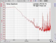
Here's another industrial switcher, a 150W Lambda LRS-53-15, rated 15V @ 10A. Putting out 16V into 4 Ohms (4A) for this test. I used this supply to power a couple of JLH amps last year but abandoned the project before I could make any judgement on how it sounded.
This test was done with a 10-bit USB scope (Cleverscope) on the 30mV range and you can see it has plenty of dynamic range for this test. Even an 8-bit with averaging will probably produce useful data.
This test was done with a 10-bit USB scope (Cleverscope) on the 30mV range and you can see it has plenty of dynamic range for this test. Even an 8-bit with averaging will probably produce useful data.
Attachments
Too often overlooked, almost everywhere...... while at it, and if possible, capture the RF rubbish spectrum these SMPS spit back into mains.... easily overlooked. I found the SMPSs are quite bad in this regard.
May well be worth it to add one or two more audio gear in the normal listening chain and measure system output. That's a fair amount of combinations of PSUs to investigate already.
If you get interested in line level audio gear powered by wall wart / laptop brick sized SMPS's, the $10 SMPS filter kit in the diyAudio Store might be worth experimentation. Max DC voltage is +48V and max DC current is 3 amperes. In-to-out DC resistance is 100 milliohms. Plus of course the voltage drop across whatever cables and connectors you use in your test fixture.
The Store kit might perhaps be of interest because it's a four pole filter, using two RLC lowpass filters in series cascade. In theory this gives quite a lot of attenuation at wall wart SMPS switching frequencies (50kHz to 300kHz). But try it yourself and see. And oh by the way, there's no "specification" provided except pay your ten dollars, try it yourself and see if you're pleased. Circuit schematic, parts list, and PCB Gerbers are on the Forum . . . in case you prefer to do the purchasing yourself, either because Store shipping fees are unacceptable to you, or because you plan to build more than one filter and can take advantage of quantity discounts on components and PCBs.
If you believe in circuit simulation, the filter is perhaps a nice candidate since it contains only eight components, all of them passive. Oh yes, plus one unidirectional TVS overvoltage protection diode, that never turns on. Just make sure you characterize your passive parts so you correctly include the parasitic capacitance of inductors and the parasitic inductance of capacitors. And of course, definitely include the equivalent series resistance of each. Luckily the components in the Store parts list, have manufacturer's datasheets which helpfully include information that shrewd engineers can use to calculate these parasitic values. Bourns inductors and KEMET low-Z electrolytic capacitors.
Last edited:
The XP Power LCS50US15 plot shows a strong signal just below 2kHz, along with harmonics - if that response is typical of that supply (and not a fault) then yes something is definitely below par with its design. I would expect very few commercial supplies to generate such specific high level signals in the audio range.
For sure all the smps with switching freq below 96kHz will show a signal at their switching frequency and its harmonics (if within the bandwidth of the measurement setup, so typically 96kHz max).
I'd suggest that a loopback plot is also shown as a benchmark, whereby the probe tip is grounded at the point where the probe ground is connected to an operating power supply, as that will indicate how well the measurement setup is performing (or not). Such a measurement may be tainted by the DAC performance of the soundcard, but it should give confidence that the frequency response of the setup is nominally flat. I'd also suggest making a measurement of a say 1kHz test signal of circa 10-100mV (as measured by an rms voltmeter), and noting the measured dBV as a sanity check of what levels people are looking at.
I'd also note that very few will have an actual dedicated spectrum analyser (ie. with spectrum above 100kHz), and not everyone with a soundcard will have a 192kHz sampling rate (so up to 96kHz bandwidth)
If anyone wants to make and post additional measurements besides output noise, please do. The point of this thread is to document what's out there so we know what models to avoid and which are good. If units have significant anomalies within the audio bandwidth, no filter we'd want to use can rectify it (pun intended).
@trobbins' sugestions are good for folks to establish confidence in their measurement setup. But I don't think the results need to be posted here.
The Meanwell brand seems to be a forum favorite so let's see some noise spectra!
@trobbins' sugestions are good for folks to establish confidence in their measurement setup. But I don't think the results need to be posted here.
The Meanwell brand seems to be a forum favorite so let's see some noise spectra!
jbau, were you able to confirm your measurement setup had negligible noise frequencies and a flat loopback response (or flat response using an alternative signal generator), and that the circa 2kHz signal from the XP Power LCS50US15 gave a 2mVrms reading on a suitable meter ?
- Home
- Amplifiers
- Power Supplies
- Post you SMPS noise spectrum measurements