hi all
i am getting some bits together to try this out but cannot source the BF245B fet in the uk (mouser only sells multiples of 7000!!!!) so could I substitute it with 2SK170BL ?
cheers
i am getting some bits together to try this out but cannot source the BF245B fet in the uk (mouser only sells multiples of 7000!!!!) so could I substitute it with 2SK170BL ?
cheers
Last edited:
any comparable Jfet
look at minimal allowable Uds at desired Iq , it's sort of critical in position in shunt reg for buffers
look at minimal allowable Uds at desired Iq , it's sort of critical in position in shunt reg for buffers
bf245b and 2sk170bl are very different jFETs.hi all
i am getting some bits together to try this out but cannot source the BF245B fet in the uk (mouser only sells multiples of 7000!!!!) so could I substitute it with 2SK170BL ?
cheers
the 245 is a low gm, high Vp device
the 170 is a high gm, low Vp device.
There are very many Nchannel jFETs that are similar to the 245.
There are very few Nchannel jFETs that are similar to the 2sk170bl. I know of only two, the LSK170b and the BF820
I must have some 2n5459 somewhere but thought the 2sk170 would perform a little better? (plus i have loads of them!)
the LSK170b and the BF820
The BF820 is a bipolar transistor, not a N-channel JFET.
i think the BF256B will be a good substitute the 2sk170 has probably too much gain for this application since it will be driving a darlington
The BF820 is a bipolar transistor, not a N-channel JFET.
I think andrew meant the BF862
Yes, thanks for correcting that.I think andrew meant the BF862
hi, i am very late for this project,
btw... just collecting some parts...


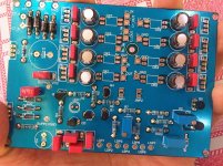
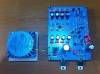
about the transformer wiring, i have soldered four diodes, is that TR wiring correct?
and, this volume control is 10K optical volpot
how about if we want it into 100K optical volpot,
are there any parts should be adjusted or only change the pot into 100K?
thanks. 😉
btw... just collecting some parts...


about the transformer wiring, i have soldered four diodes, is that TR wiring correct?
and, this volume control is 10K optical volpot
how about if we want it into 100K optical volpot,
are there any parts should be adjusted or only change the pot into 100K?
thanks. 😉
first question - no , not correct
look at top left corner , on penultimate page in Cook Book - remove two diodes , connect it as center tap , center tap to gnd
second question - page 22 lower half , few more facts
look at top left corner , on penultimate page in Cook Book - remove two diodes , connect it as center tap , center tap to gnd
second question - page 22 lower half , few more facts
Hi ZM,
i have read the cook book, thanks.
about the transformers, wasn't there are two options? (CT and nonCT)
and in my case, 4 diodes are soldered, so i make the dual sec trafo into single out by paralleling the outputs.
(sorry, i'm not patronizing) 😀
btw still need to make sure if everything okay.

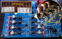
about the LDR orientation,
and the LDR match pairing positions,
whether it is appropriate?
thanks.
Pete
i have read the cook book, thanks.
about the transformers, wasn't there are two options? (CT and nonCT)
and in my case, 4 diodes are soldered, so i make the dual sec trafo into single out by paralleling the outputs.
(sorry, i'm not patronizing) 😀
btw still need to make sure if everything okay.

about the LDR orientation,
and the LDR match pairing positions,
whether it is appropriate?
thanks.
Pete
Last edited:
naah , you're not patronizing ...... I just don't like direct paralleling of secondaries, except in case when I know for sure that windings are bifillary wound ; that's why we made those options
regarding placement and orientation , you got it right , according to your pictures
regarding placement and orientation , you got it right , according to your pictures
except in case when I know for sure that windings are bifillary wound ; that's why we made those options
i see...
regarding placement and orientation , you got it right , according to your pictures
okay ZM, ready to fire then.
almost forgot, some friends said about the component used behind the LDR,
are the quality component used can really pass through the light?
so as the result, we really can hear the character of component being used.
.....
almost forgot, some friends said about the component used behind the LDR,
are the quality component used can really pass through the light?
so as the result, we really can hear the character of component being used.
those friend of yours are definitively in Audiophool camp

only distortion you can hear there is from resistor inherent nonlinear distortion ...... some like it more than common contact based attenuators , some not ......... and fact is that , with sane voltage levels , this type is sounding cleaner .
me personally , I prefer inductive based attenuators and euphony they bring
those friend of yours are definitively in Audiophool camp
ROTFL

i also really doubt about it.
or maybe personally they have a super maniac ear. 😀😀😀
me personally , I prefer inductive based attenuators and euphony they bring
ah... another toy.
not now, but noted. (anxious level up) 🙄
thanks ZM.

Some friends told me that I should set my clocks different becakuse the in the the hardware being used was made in another timeframe. Is that true? Will the music play bacwards if I change the polarity of my cables?. Is Jesus really coming back?
- Home
- Source & Line
- Analog Line Level
- Poor Serbian Man Optical Volume Control