This may be a completely retarded question ... but I am unsure... so what exactly does buffered and unbuffered mean? I have both PCB's... Does buffered lend itself better to certain setups and unbuffered others? or is buffered usually better than unbuffered? If so would I even need a set of XLR out that are unbuffered or can I just wire those outputs off PCB 1 directly to PCB 2?
My idea of when using a buffer :
-passive attenuators (10K) with long shielded interconnects
-if sources have a large outputimpedance
-if your amp has a low inputimpedance
you have to measure it together with source/pre/poweramp if you need a buffer
A buffer is ideal, infinite imputimpedance and very low outputimpedance.
If needed, you get more bass, more db's at low volume and better resolution. Try it between source and pre and pre and poweramp.
I have a 50k attenuator with short unshielded interlinks, so no benefit from the buffer, seems to be an impedancematch. Maybe I need it when using the lightspeedattenuator, but i rather not want to use a buffer, as less active parts in the signalway as possible...
This may be a completely retarded question ... but I am unsure... so what exactly does buffered and unbuffered mean? I have both PCB's... Does buffered lend itself better to certain setups and unbuffered others? or is buffered usually better than unbuffered? If so would I even need a set of XLR out that are unbuffered or can I just wire those outputs off PCB 1 directly to PCB 2?
acidbrain basically explained everything. 🙂
There are a plenty of possibilities.
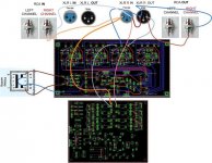
You can use only PCB01 (means unbuffered), or You can use only Buffered (PCB01 & PCB02), or You can have a both (as shown on wiring diagrams), and use what You find the best in Your current setup. If setup is changed, maybe you'll find other combination works better. It's up to You to make a decission.
Last edited:
awesome info thanks! I think I'll buld both ... its only going to cost me an extra set of XLR plugs since I have both PCB's already then I can have the added flexibility! I appreciate all the help, I love this site and all the people here!
awesome info thanks! I think I'll buld both ... its only going to cost me an extra set of XLR plugs since I have both PCB's already then I can have the added flexibility! I appreciate all the help, I love this site and all the people here!
NBA Slogan : "I love this game"

You would be surprised that's even possible to have mixed RCA/XLR...but that idea still sits in ZM head 🙂
Enjoy building it, I'm shure You'll be satisfied.
Maybe I need it when using the lightspeedattenuator, but i rather not want to use a buffer, as less active parts in the signalway as possible...
Have in mind, PCB01 with all active elements is nothing to be warried, because musics travel through PCB01 only via the passive (variable) LDR photo sensitive resistors. GND trace on PCB01 is totally separated and basically not conected to the Analog GND.

Please, don't forget the Heatsinks where needed (on both PCBs)
An externally hosted image should be here but it was not working when we last tested it.
An externally hosted image should be here but it was not working when we last tested it.
NBA Slogan : "I love this game"
You would be surprised that's even possible to have mixed RCA/XLR...but that idea still sits in ZM head 🙂
Enjoy building it, I'm shure You'll be satisfied.
I was thinking about that, could I pull Gnd and + off the XLR and daisy chain it to an RCA?
I was thinking about that, could I pull Gnd and + off the XLR and daisy chain it to an RCA?
You mean... something like this 😎
p.s. Exclusive use : XLR or RCA, in this case😉
Attachments
You mean... something like this 😎
p.s. Exclusive use : XLR or RCA, in this case😉
exactly, exclusive use.. that should be ok?
there is no better way than daisy-chain ;
off course - when using mixed mode (unbal in/bal out or bal in/unbal out ) one must take all usual precautions regarding neg leg grounding

I wanted to close some loose ends first😀
http://www.diyaudio.com/forums/showthread.php?p=1947236&posted=1
But will continue on monday with the lightspeed, anxious to hear the difference between it and my Dale attenuator.
http://www.diyaudio.com/forums/showthread.php?p=1947236&posted=1
But will continue on monday with the lightspeed, anxious to hear
the difference between it and my Dale attenuator.Hello
Question to ZM:
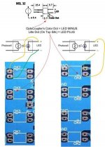
Concerning the Kit: LDR marked with Series 1 -4 are OK 1/3/5/7
ans LDR Parallel 1 - 4 are OK 2/4/6/8
Right?
so LDR Series 3 will be soldered to OK 5 And LDR Parallel 2
at Solderjoints OK 4
What about BC546C will there be disadvantage if i use BC546B instead?
Greetings Ulf
Question to ZM:
Concerning the Kit: LDR marked with Series 1 -4 are OK 1/3/5/7
ans LDR Parallel 1 - 4 are OK 2/4/6/8
Right?
so LDR Series 3 will be soldered to OK 5 And LDR Parallel 2
at Solderjoints OK 4
What about BC546C will there be disadvantage if i use BC546B instead?
Greetings Ulf
Hello
Question to ZM:
Concerning the Kit: LDR marked with Series 1 -4 are OK 1/3/5/7
ans LDR Parallel 1 - 4 are OK 2/4/6/8
Right?
so LDR Series 3 will be soldered to OK 5 And LDR Parallel 2
at Solderjoints OK 4
What about BC546C will there be disadvantage if i use BC546B instead?
Greetings Ulf
yup ;
quoting Mighty ZM from (still unfinished ) Cook Book :
If you obtained your LDRs from me – use SeriesX and Shunt X as pair , where X is 1 to 4 ; so – Series1+ Shunt1 , Series2 +Shunt2 , Series3 + Shunt3 ,Series4 + Shunt4 ; they’re matched with that in mind .
off course that pairs are OK1 & OK2 , OK3 & OK4 , OK5 & OK6 , OK7 & OK8 ;
tnx for asking - I'll include that further clarification in Cook Book .
regarding B or C suffix for little critters - there is a rumor that - from ancient times of Philips BC transistors , no-one is really making C range - they're just re-branded B range ;
so - use whatever you have in drawer
this must be wrong.there is a rumor that - from ancient times of Philips BC transistors , no-one is really making C range - they're just re-branded B range ;
so - use whatever you have in drawer
Specifications and measurements show that b and c grade are different.
- Home
- Source & Line
- Analog Line Level
- Poor Serbian Man Optical Volume Control