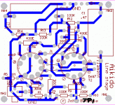
Just mirror the pcb..I think?
http://www.tubecad.com/2004/MoreAikido4.gif
and you could just share the 0,47uF-100k-100k noise divider
http://www.tubecad.com/2004/MoreAikido4.gif
and you could just share the 0,47uF-100k-100k noise divider
Bonny_kjs could you add a potmeter next to R9? That way we can add the noise reduction "tweak" as offered by member rdf.
And maybe a tp /pin next to R9 as well...as I drew on your pcb...this way the "noise bridge" can be shared between channels if people want to save a few pennies on a cap and resistors..or if they want to share it between their 2 mirrored pcb's so they can go balanced.
http://www.diyaudio.com/forums/showthread.php?postid=680209#post680209
Attachments
Hi
1. Capacitor size reduced.
2. Test point provided.
3. R2 and R9 tilted to bring them closer to tube pins.
4. most of connection brought to the back edge of PCB.
What are the tracks where potmeter connections will go?
The new pdf file show actual size of one channel of PCB. The size has become still smaller 95mm X88mm
regards
Anybody know how to calculate the output impedance of these Aikido stages? Is it just rp+Rp||rp+Rp or is that too simple?
Found this over at AA posted by 01A
Zo=(rp/mu+1)+Rk||(rp(mu+1)Rk)
bonny_kjs
Would it be too much trouble to make the tube socket layout so that one could use either the 5687/7119/E182CC or 6N1P/ECC99/6922/12xxx/6H30P pinout?
I think this could be done by placing a jumpered break just off of pins 6,8,9 so one could just jumper the pins for the tube used.
The reasoning behind this is so that the user could use the best tube for the application. I can see people using this modular PCB for line stages, phono stages, DAC outputs and power tube drivers at least.
I am also interested in the PCBs.
Since many are interested in the PCBs, should you experts also consider providing more detailed info for the newbies (me included), such as selecting the best possible tubes and optimising the filament supply, in order to make it easier for the newbies to take on this Aikido project?
(1). Let's say we use medium mu triodes. Soundwise which tube is most suitable for the VA - 6SN7? 6DJ8? 12BH7? etc. Which tube for the CF - 6SN7? 5687? 12AT7? Tube rolling may be fun but that costs money and I wish I could just select the right tubes going for first class for the first time.
(2). So far it has basically come to a conclusion that the top and bottom tubes should use one twin triode for the best possible match. This leads to using one filament supply voltage to both tubes. Let's say B+ is 300VDC then the bottom tube is operating between 0 to 150V and the top tube between 150V to 300V. How high should the DC filament voltage be raised to for optimal performance and tube life? Let's say DC is used.
Regards,
Bill
I have an idea. How about put the two tube sockets on a daughter board and connect to the main board with the rest of the components using either an edge connector or some kind of socket connectors.
This way, people can use different socket pinouts by swapping the daughter board.
This way, people can use different socket pinouts by swapping the daughter board.
dshortt9 said:bonny_kjs
Would it be too much trouble to make the tube socket layout so that one could use either the 5687/7119/E182CC or 6N1P/ECC99/6922/12xxx/6H30P pinout?
I think this could be done by placing a jumpered break just off of pins 6,8,9 so one could just jumper the pins for the tube used.
The reasoning behind this is so that the user could use the best tube for the application. I can see people using this modular PCB for line stages, phono stages, DAC outputs and power tube drivers at least.
Hi Dshortt9
I will look into the possibility of providing jumper for using
various tubes.
regards
I will look into the possibility of providing jumper for using
various tubes.
regards
That would be neat...after that we have the jumpers in we would be ready for production AFAIC.I will look into the possibility of providing jumper for using
(1). Let's say we use medium mu triodes. Soundwise which tube is most suitable for the VA - 6SN7? 6DJ8? 12BH7? etc. Which tube for the CF - 6SN7? 5687? 12AT7? Tube rolling may be fun but that costs money and I wish I could just select the right tubes going for first class for the first time.
Just a very very rough guide...
Typically
VA=6SN7/6DJ8/6N1P/ECC88/6922
CF=5687/ECC99/7119/E182CC
but any of the VA could easily fit in the CF position as well.
Typically heater cathode insulation can handle 100V potential difference. up or down. (Check the heater/cathode insulation for your tube) So if you have a b+ of say 300vdc..the cathode of the upper tube will be around 150V. So biasing up to anywhere between 75v - 100v should be good.How high should the DC filament voltage be raised to for optimal performance and tube life?
I just read this http://www.tubecad.com/ContactInfo.htm
John does not read forums, and wants us to respect that.
I think therefore that he won't answer us or will check out this thread.
AFAIK know we have no legal obligations when doing a group buy of a pcb designed by one of our members.. John's articles are in the public domain. And we are not allowed to copy and publish his journal. But we can use his schematics all we like for our own personal pleasure? 😉.. as long as there is no financial incentive for our endeavours.. I see no moral objections either.
Please tell me what you guys think?
I've just sent another email to John Broskie asking for his permission again and offering to maybe raise a surcharge on the pcb's to support his work on tubecad.com
BAS, bonny_kjs
Looks Great! Very flexible. If you could add a tie point at pin 9 of the first tube it would serve for the filament CT depending on the tube used. Awesome! I would be ready to order.
Concerning John Broskie - I have learned so much from his Blog and programs that I would be willing to pay a surcharge to support his efforts.
Member
Joined 2002
Id also be interested in some boards. I can see buti could also be wrong there is a balanced version ? Ill take 4 2 none balanced and 2 balanced. : O ) Good job on the board's
- Home
- Amplifiers
- Tubes / Valves
- Poll..anyone interested in an Aikido linestage PCB group buy?

