William, Alessandro Dalto, Von Ah, and Mark Johnson. Thank you for the aspirin and advertisement free advice. John

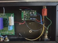
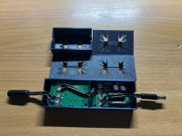
I had originally built my B1 buffer in this enclosure with a small toroid and LM317 regulator. A month ago I decided to move the B1 to a different enclosure and put a different circuit in here. Which required an external power supply connected through a barrel jack. Well, the new circuit was just a little too cramped for my liking so I put the B1 back in. I decided to stick with the barrel jack as it allowed me to use a low voltage external supply. Which in turn allowed me to use one of those cool looking "halo light" switches. And when I saw william2001 sharing his PO89ZB boards I jumped on the offer. Here it is implemented. I can't hear any negative impact vs using the linear regulated power supply. Thank you, Mark Johnson, for sharing the design with us and thanks again to william2001 for sharing your boards!
Attachments
thirdicomples... very novel.
- Absolutely very curious about your use of the "halo light" switches. I have never heard of them.
- If you really found them fantastic, will you share the "where to buy and any cavoites to install"
John
- Absolutely very curious about your use of the "halo light" switches. I have never heard of them.
- If you really found them fantastic, will you share the "where to buy and any cavoites to install"
John
If you're interested in switches like the ones below, I found them on Amazon and DigiKey and (especially) Newark, using the search phrase "anti vandal". Beware, >90% of them are not mains rated; voltage too low and current waaaay too low. One common workaround is to connect the wimpy A.V. switch to a pcb like H9KPXG on this site, Intelligent Soft Start on neurochrome.com, project 166 on Elliott Sound Products website, etc. Anti vandal switch controls a second, much beefier, mains-rated switch of some sort (triac, relay, etc), which is not on the front panel.
_
_
Attachments

@Mark Johnson Does it make sense to use 2 P089ZB boards to filter the output of a dual SMPS, one inline with V+, one inline with V-?
Or is there a more integrated solution?
Or is there a more integrated solution?
This design does not have the diodes, but you can add the diodes manually.
In this post you will find the info for the second negative board.
Also found 540, which seems like exactly what I was looking for.
For those who are considering designing their own SMPS filter circuits, I recommend starting with a thorough understanding of self-resonance. As mentioned in post #9 of this thread, the inductors in PO89ZB exhibit self-resonance, and so do the electrolytic capacitors. If you can discover their self-resonant frequencies, you can calculate the (parasitic) self-capacitance of the inductor -- and you can also calculate the (parasitic) self-inductance of the electrolytic capacitor {often called "ESL" here on diyAudio}.
The inductor's self resonant frequency f_SRF_ind is equal to
Similarly, the electrolytic capacitor's self resonant frequency f_SRC_cap is equal to
The good news is, inductor manufacturers usually include the self resonant frequency on their datasheets. All you have to do is look it up. For example, the Bourns inductors used in PO89ZB have a self resonant frequency of 63 MHz, as printed on their datasheet. So now you can calculate the C_parasitic of these inductors. Oh boy!
The not so good news is, electrolytic capacitor datasheets usually DO NOT include the self resonant frequency. You have to measure it yourself.
And the silver lining good news is, it turns out that you can measure it yourself pretty easily. Prolific electronics YouTuber "w2aew" shows how in his video #100, entitled "Capacitor self-resonance measured with an oscilloscope and signal generator". Set up the gear the same way he does, take the measurements the same way he does, and presto! You've got the measured self-resonant frequency of your electrolytic capacitor. Not the estimated S.R.F. Not the rectally-extracted S.R.F. wild guess from somebody you barely know. Not the lazy reliance on third-hand foggy memories, "usually things are sorta in the ballpark between X and Y". You've got measured S.R.F. So now you can calculate the L_parasitic of these capacitors.
And now you can run a precise analysis of your filter including its parasitics, to see exactly how well it removes HF noise and to see how poorly it damps its own undesired resonances.
The inductor's self resonant frequency f_SRF_ind is equal to
- f_SRF_ind = 1 / (2 * pi * SQRT(L_inductor * C_parasitic))
Similarly, the electrolytic capacitor's self resonant frequency f_SRC_cap is equal to
- f_SRF_cap 1 / (2 * pi * SQRT(C_capacitor * L_parasitic))
The good news is, inductor manufacturers usually include the self resonant frequency on their datasheets. All you have to do is look it up. For example, the Bourns inductors used in PO89ZB have a self resonant frequency of 63 MHz, as printed on their datasheet. So now you can calculate the C_parasitic of these inductors. Oh boy!
The not so good news is, electrolytic capacitor datasheets usually DO NOT include the self resonant frequency. You have to measure it yourself.
And the silver lining good news is, it turns out that you can measure it yourself pretty easily. Prolific electronics YouTuber "w2aew" shows how in his video #100, entitled "Capacitor self-resonance measured with an oscilloscope and signal generator". Set up the gear the same way he does, take the measurements the same way he does, and presto! You've got the measured self-resonant frequency of your electrolytic capacitor. Not the estimated S.R.F. Not the rectally-extracted S.R.F. wild guess from somebody you barely know. Not the lazy reliance on third-hand foggy memories, "usually things are sorta in the ballpark between X and Y". You've got measured S.R.F. So now you can calculate the L_parasitic of these capacitors.
And now you can run a precise analysis of your filter including its parasitics, to see exactly how well it removes HF noise and to see how poorly it damps its own undesired resonances.
If you haven't yet read post #2,277 over in the DIY ACA mini thread, I think you probably will enjoy it. That post includes a photo which I have copied below. Cowabunga!
_
_
Attachments
@william2001 Will you consider shipping them to India? I need all 5 if possible.I have 5 boards left.
(update from post #1,054..)
Mark, can you measure any benefits this combo brings electronically?If you haven't yet read post #2,277 over in the DIY ACA mini thread, I think you probably will enjoy it. That post includes a photo which I have copied below. Cowabunga!
_
Thanks,
Pete
I have not tried that. But please feel free to perform the experiment yourself if you're dying of curiosity! See post #943 for one approach to test apparatus.
Do you still have any boards left?I have 5 boards left.
(update from post #1,054..)
Plenty of them available here:
https://diyaudiostore.com/collections/kits-power-supply/products/smps-dc-filter-p089zb-kit
https://diyaudiostore.com/collections/kits-power-supply/products/smps-dc-filter-p089zb-kit
I sent 300 to the store a couple of weeks back and they appear to be in stock.
- Home
- Source & Line
- Analog Line Level
- PO89ZB, an inline DC filter for SMPS wall warts. Preamps, HPA, Korg NuTube, etc