I got around this problem by using the XPPower ECL series AC/DC units which don't have a max specified capacitance
I got around this problem by using the XPPower ECL series AC/DC units which don't have a max specified capacitance
I want to put a BA2018 preamp board into the chassis designed for the B1K and use the existing B1K 24V 1A wall wart. I have chosen the Mean Well DKM10B-15 which has, other than the capacitance limit, pretty ideal specs for my purpose. However, the spec says maximum 60mv ripple and I'd like to drastically reduce that with this filter.
You could try it. In my experience with similar Meanwell smps is that if they see too much capcitance on their o/p the overcurrent protection trips and they switch off only to switch on again when the current drops. This cycle goes on until the o/p cap is fully charged. They call it "hicoughing" . It works but I wouldnt like to use something always doing that but it would tell you if the o/p capcitance is too large.
I would like to use this filter after an smps that specifies a maximum of 330uF can be added at the output.
Not really understanding the details of the interaction between the resistors, inductors, and capacitors on this board, I am wondering how much capacitance the source to the board "sees" and if this filter meets that 330uF specification?
Unfortunately, during the powerup inrush event, the PSU "sees" all 940 microfarads of capacitance on the inline filter board, PLUS all of the microfarads on the board(s) inside the DAC or headphone amp or Raspberry Pi or whatever gear is drawing DC power from the PSU.
If you connect this filter to your max-330uF PSU, the PSU will almost certainly enter its overcurrent-protect mode during startup inrush. Some PSUs implement "hiccup" mode, in which they wait a while after overcurrent, then try again. If the load current is still too large, they wait a while and try again a third time, etc.
On the other hand, looking at this as a hobbyist not a hand wringing worrywart: SMPSs are cheap and this filter is even cheaper, so why not just try it and see what happens? The worst case outcome is a blown SMPS and a blown filter board, both of which are inexpensive to replace.
_
If you connect this filter to your max-330uF PSU, the PSU will almost certainly enter its overcurrent-protect mode during startup inrush. Some PSUs implement "hiccup" mode, in which they wait a while after overcurrent, then try again. If the load current is still too large, they wait a while and try again a third time, etc.
_
As I understand it, the preamp draws 25mA per channel per voltage (+/-), plus 10mA per voltage for the volume control so I only need 35mA per voltage (50mA to be safe) and the smps delivers 333mA max per voltage.
Would it be reasonable to insert a resistor or other device of some value between the smps and the filter board to limit current inrush? Would that disrupt the filtering?
Smps hiccup
From past experience in the Western Electric #5ESS telephone switch. We had large filter capacitors behind a fuse which would blow every time a fuse was replaced. This was done by design as a larger fuse would not offer the desired protection. To get around the problem we had a charging tool. This tool was basically a current limiter. We waited for the capacitor to charge an then reinserted the fuse. A simple circuit with a inrush limiter and a bypass relay would do the trick. Just a suggestion. Hope this helps.
From past experience in the Western Electric #5ESS telephone switch. We had large filter capacitors behind a fuse which would blow every time a fuse was replaced. This was done by design as a larger fuse would not offer the desired protection. To get around the problem we had a charging tool. This tool was basically a current limiter. We waited for the capacitor to charge an then reinserted the fuse. A simple circuit with a inrush limiter and a bypass relay would do the trick. Just a suggestion. Hope this helps.
I would be interested in building a low-current +/- version of this filter for use in my preamps.
It seems to me that as long as I use the same-value components I could save some space by using a lower voltage capacitor (470uF 25V) and a 2.2uH 0.1R low current SMD inductor? That would keep the circuit electrical characteristics the same and would operate properly, would it not?
It seems to me that as long as I use the same-value components I could save some space by using a lower voltage capacitor (470uF 25V) and a 2.2uH 0.1R low current SMD inductor? That would keep the circuit electrical characteristics the same and would operate properly, would it not?
Mark is probably the best one to respond to that, but meanwhile if I may...
Sadly there is probably a bit more to it, although it looks very simple, this is the real Mc Coy with garanteed results.
We had initialy a given cap, and later moved on to a lower esr one and it still worked better. Caps, coils aren't perfect, they are modelled in a certain way and that circuit has taken care of these "imperfections" (caracteristics in fact), hence some additional parts to dampen unwanted resonnances of the coils etc.
Short answer is "it is unlikely to create damage unless very unlucky with resonnances, but no one can garantee you it will work as intented with other components".
Sorry, all IMHO
Claude
I just went looking for low ESR capacitors to build a few of these -- there seems to be a worldwide zero availability at the moment with restocking scheduled in 2022!
If lower-ESR capacitors make a substantial difference in the effectiveness of the filter, would there be an advantage to paralleling a small value film or ceramic capacitor with each electrolytic?
I'm still working on the idea of using a +/- 333mA supply with the po89zb filter on each leg for the BA2018 preamp and somehow getting around the initial power surge challenge. So far, the best/easiest solution seems to be to use resistors in the plus & minus lines to limit initial surge current plus a small relay to connect the PS directly to the capacitance after the surge has subsided.
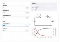
I've looked at the time constants for resistance and anticipated capacitance (1200uF or thereabouts per side) and am trying to decide what value resistor to use.
Given a 15 volt initial differential, I could use a resistor of about 45 ohms to deliver full supply current to charge the caps, or a greater resistance of maybe 75 ohms for a 200mA initial surge. Either way, the surge lasts well under one second (see attached), and the 45 ohm resistor handles a momentary 5 watt load and the 75 ohm resistor handles 3 watts.
Question I have is, given the very brief period of high wattage, how small a wattage resistor can I get away with?
Can anyone help me with this?
Attachments
Last edited:
I just went looking for low ESR capacitors to build a few of these -- there seems to be a worldwide zero availability at the moment with restocking scheduled in 2022!
Hi Wapo,
You may just consider buying the kit from the DIY Store which includes all of the parts including the Low ESR caps.
SMPS DC Filter P089ZB Kit – diyAudio Store
I've looked at the time constants for resistance and anticipated capacitance (1200uF or thereabouts per side) and am trying to decide what value resistor to use.
Given a 15 volt initial differential, I could use a resistor of about 45 ohms to deliver full supply current to charge the caps, or a greater resistance of maybe 75 ohms for a 200mA initial surge. Either way, the surge lasts well under one second (see attached), and the 45 ohm resistor handles a momentary 5 watt load and the 75 ohm resistor handles 3 watts.
You've made excellent progress, and have done some fine work thus far: Congratulations! In a slight twist upon a well known aphorism, I very much enjoy helping those DIYers who help themselves. So let's have a look at some follow-on calculations, together.
Firstly, if the SMPS promises not to current-limit until 333 mA, why not allow the inrush current to be 90% of CurrentLimit? This gives the mfr some leeway and provides a 10% "tolerance guardband" upon his datasheet spec.
So: (15V + 10%) / Rseries = (90% * 333mA) ---> solution: Rseries = 55.1 ohms
Round up to nearest EIA standard value: 56 ohms.
Maximum instantaneous power = (15V + 10%)^2 / 56 = 4.86 watts
Resistor datasheets such as the attached, all seem to say that the short term overload voltage is 2.5X the "RCWV", i.e., 2.5X the square root of (PowerRating * ResistanceValue). Okay, that's nice to know, but what we're interested in here is the short term overload power rather than the short term overload voltage. And math comes to the rescue: since power dissipation is proportional to the square of voltage, the short term overload power is (2.5 squared) = 6.25X the continuous power rating. That's the number we seek.
We now know that you want a resistor whose continuous power rating is greater than (4.86 watts / 6.25X) = 0.77 watts.
I myself would choose a 2 watt resistor, because 2 watts is comfortably greater than 0.77 watts. Maybe you want even more safety margin; maybe you can live with less. 2 watts is what it takes to make me feel adequately protected against undesired outcomes.
_
Attachments
Last edited:
Mark, I really appreciate the help with this problem! I see your logic but could not have known how to figure that out for myself. I’ll take this advice and the process and continue to work on this.
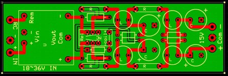
My first cut at making a compact +/- power supply with a DC-DC converter and a filter on each leg. PCB is currently 4.050 x 1.3 inches.
Hopefully the relay will work with just a zener in series and connect after the capacitors on both legs are approaching full voltage.
Edit: Diode reversed, will fix.
Hopefully the relay will work with just a zener in series and connect after the capacitors on both legs are approaching full voltage.
Edit: Diode reversed, will fix.
Attachments
Last edited:
You've made excellent progress, and have done some fine work thus far: Congratulations! In a slight twist upon a well known aphorism, I very much enjoy helping those DIYers who help themselves. So let's have a look at some follow-on calculations, together.
Firstly, if the SMPS promises not to current-limit until 333 mA, why not allow the inrush current to be 90% of CurrentLimit? This gives the mfr some leeway and provides a 10% "tolerance guardband" upon his datasheet spec.
So: (15V + 10%) / Rseries = (90% * 333mA) ---> solution: Rseries = 55.1 ohms
Round up to nearest EIA standard value: 56 ohms.
Maximum instantaneous power = (15V + 10%)^2 / 56 = 4.86 watts
Resistor datasheets such as the attached, all seem to say that the short term overload voltage is 2.5X the "RCWV", i.e., 2.5X the square root of (PowerRating * ResistanceValue). Okay, that's nice to know, but what we're interested in here is the short term overload power rather than the short term overload voltage. And math comes to the rescue: since power dissipation is proportional to the square of voltage, the short term overload power is (2.5 squared) = 6.25X the continuous power rating. That's the number we seek.
We now know that you want a resistor whose continuous power rating is greater than (4.86 watts / 6.25X) = 0.77 watts.
I myself would choose a 2 watt resistor, because 2 watts is comfortably greater than 0.77 watts. Maybe you want even more safety margin; maybe you can live with less. 2 watts is what it takes to make me feel adequately protected against undesired outcomes.
_
I wanted to second Mark's earlier recommendation to just try things after you do the analysis. The math exercise here is indeed excellent and how you design this stuff, but do not forget the practical aspect of actual testing. We discovered this recently with the ACP+ kit PSUs which stated a current rating of 1A, but would not push through the first 1000uF cap that had a resistor in front thus limiting inrush current and initial capacitance to what we thought would be easily acceptable to the PSU, but instead only ran in a loop of hiccup mode. Not all PSUs are implemented to the same specifications, whether printed on the tin/datasheet or not. 😉
--Tom
You've made excellent progress, and have done some fine work thus far: Congratulations! In a slight twist upon a well known aphorism, I very much enjoy helping those DIYers who help themselves. So let's have a look at some follow-on calculations, together.
Firstly, if the SMPS promises not to current-limit until 333 mA, why not allow the inrush current to be 90% of CurrentLimit? This gives the mfr some leeway and provides a 10% "tolerance guardband" upon his datasheet spec.
So: (15V + 10%) / Rseries = (90% * 333mA) ---> solution: Rseries = 55.1 ohms
Round up to nearest EIA standard value: 56 ohms.
Maximum instantaneous power = (15V + 10%)^2 / 56 = 4.86 watts
Resistor datasheets such as the attached, all seem to say that the short term overload voltage is 2.5X the "RCWV", i.e., 2.5X the square root of (PowerRating * ResistanceValue). Okay, that's nice to know, but what we're interested in here is the short term overload power rather than the short term overload voltage. And math comes to the rescue: since power dissipation is proportional to the square of voltage, the short term overload power is (2.5 squared) = 6.25X the continuous power rating. That's the number we seek.
We now know that you want a resistor whose continuous power rating is greater than (4.86 watts / 6.25X) = 0.77 watts.
I myself would choose a 2 watt resistor, because 2 watts is comfortably greater than 0.77 watts. Maybe you want even more safety margin; maybe you can live with less. 2 watts is what it takes to make me feel adequately protected against undesired outcomes.
_
@Thomas, yes I agree also. I have a Korg B1 which has an odd turn-on behavior that I didn't understand before but I now believe is the over-current phenomenon -- when I turn it on the power LED first comes on bright, then dims to nothing, then comes back on.
I thought about the inrush current limiting resistor -- the difference between 300mA inrush and, say, 200mA inrush per leg is less than one second in real time, so I'm going with the more conservative approach. After the capacitors charge, the relay will kick in and bypass the resistors so initial value isn't that important.
PCB is coming along. Realized zener is not appropriate here, replaced with a resistor for a voltage divider to drive the 24V (18V "must switch") relay. Also shortened the traces to more like optimal. Board is now 4.0 x 1.3 inches, still nice and small.
I have an off-topic question -- what size hole should I choose for the standoffs? I've always used .150 for myself, but now wondering if there is a "standard" that I should use?
For the standoff holes, you'll get people who tell you to use the metric or imperial ones, but its a personal preference thing. I prefer keeping things consistent across the board. I would suggest making sure they are on the outer edges of the board in a convenient place to mount it after everything is mounted. That is, make sure nothing touches the nut on top/etc....
Also consider adding positions for attaching a BNC surface mount for the best high-frequency/RF testing, or at least put that on your prototype to facilitate your pre-final board run tests. Mark explained why simply attaching regular scope probes to the circuit when testing is insufficient, as well as the need to put this inside a case that will further shield it from stray RF when testing, earlier in the thread.
--Tom
I recommend you fight a lot harder to keep signal traces off the green layer. Put everything on the red layer as best you can, and keep gigantic wide copper boulevards for electrons and holes to flow unrestrictedly, along the glassy smooth surface of the calm green lake. If necessary, move components around. Elongate axial footprints if necessary. Abandon perfect visual symmetry if necessary. It's a knife fight, use every dirty trick you can imagine.
Me, I use mounting holes that can accommodate either 4-40 or M3 bolts. Protip: look up the dimensions of the hex nut and star washer you plan to use, then lay out a mounting hole footprint whose under-the-nut copper surround is wider than either the nut or the washer. Presto: short circuits avoided.
_
Attachments

Last edited:
I recommend you fight a lot harder to keep signal traces off the green layer. Put everything on the red layer as best you can, and keep gigantic wide copper boulevards for electrons and holes to flow unrestrictedly, along the glassy smooth surface of the calm green lake. If necessary, move components around. Elongate axial footprints if necessary. Abandon perfect visual symmetry if necessary. It's a knife fight, use every dirty trick you can imagine.
Me, I use mounting holes that can accommodate either 4-40 or M3 bolts. Protip: look up the dimensions of the hex nut and star washer you plan to use, then lay out a mounting hole footprint whose under-the-nut copper surround is wider than either the nut or the washer. Presto: short circuits avoided.
_
Question on the above: Do you recommend the stand-offs contact the ground/return layer or be isolated so ground/return is only connected to the board via the specified connection points? I've seen this done both ways and you just reminded me that I've been curious about the pros/cons.
--Tom
- Home
- Source & Line
- Analog Line Level
- PO89ZB, an inline DC filter for SMPS wall warts. Preamps, HPA, Korg NuTube, etc