Bummer. I've heard that same sound and was hoping this might help. Maybe I'll get lucky, though.
If you solve it, please let me know!
Hans Beekhuyzen has some very comprehensible videos on high end pi streamers. Sure he has the hiss solved.If you solve it, please let me know!
HifiBerry DAC2 HD sound card for Raspberry Pi - YouTube
If you solve it, please let me know!
First try wired network (make sure WiFi is disabled), then try to separate the DAC from the RPI with a ribbon cable and some metal between the two.
I ordered a cheap LLC switch mode power supply from Ali Express. Now doing that is a lottery, sometimes you are surprised.
This PS is intended as a built in for an ACA so it is single voltage and 24 V.
To use the filter in an ACA I will use slightly different values for some of the components, more on that later. Also a thicker copper layer on the PCB. And one filter per channel.

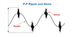
I tested it yesterday on the bench to see what I got. The voltage is stable to the second decimal between a light load and 1 A continuous, that is expected. But the noise... is interesting, 3 V peak to peak, horrible!


Putting a well known filter between the PS and the load made a difference, now it is 600mV of high frequency noise, at one ms interval....


I will see if it is possible to tune the filter to better suppress the high frequency content, but that will be a trial and error proposition for me.
This PS is intended as a built in for an ACA so it is single voltage and 24 V.
To use the filter in an ACA I will use slightly different values for some of the components, more on that later. Also a thicker copper layer on the PCB. And one filter per channel.
I tested it yesterday on the bench to see what I got. The voltage is stable to the second decimal between a light load and 1 A continuous, that is expected. But the noise... is interesting, 3 V peak to peak, horrible!
Putting a well known filter between the PS and the load made a difference, now it is 600mV of high frequency noise, at one ms interval....
I will see if it is possible to tune the filter to better suppress the high frequency content, but that will be a trial and error proposition for me.
Last edited:
Price please because standard in the switching PSU industry is to have 1% of ripple so 240mV max for +24V output. Most of known manufacturers do that. Some of them are better (<100mV of ripple).
Manufacturers like Meanwell, TDK Lambda, XP POWER have very good PSU for a good price (for me).
Another remark, noise and ripple are not the same thing. Ripple is at switching frequency (value is on the datasheet). Noise is more difficult to know by technical documentation and only an oscilloscope can sometime give the information but it needs an oscilloscope with a high bandwidth (forget 20MHz, at least 100Mhz and maybe 500MHz in some cases).
So best way for filtering is tgo design a filter for each "problem". One calculated for ripple (f ~100kH-500kHz, see datasheet for swithing frequency) and another one for noise (f > 10~50~100MHz, small capacitors value + self with a high sfr value to "go" in the very high frequency).
Attachments
Last edited:
Good points.
Yes there are better alternatives, but I see a lot of people buying there supplies, and this is after all DIY. I like to see how far I can take it and not ruining the regulation.
Low frequency ripple is resonable, I think. The high frequency not so and there is where the high peaks are. This might not be a problem in my application, but I like to tinker.
The final choice is ears 😉
And of course, it depends on application because for an amp, ripple & noise are less important than for a preamp.
And of course, it depends on application because for an amp, ripple & noise are less important than for a preamp.
The scope picture below is explained in post #515 of this thread. Click on the image to see it full size and undistorted.

Hi Mark,
Thanks as usual for all your hard work. Is a Rev. B. coming? The reason I ask is the store is out of the boards and was just wondering if they are coming back.
Cheers,
Greg
Thanks as usual for all your hard work. Is a Rev. B. coming? The reason I ask is the store is out of the boards and was just wondering if they are coming back.
Cheers,
Greg
This is great! Hope there are no problems stealing this and integrating it into my board 🙂
Any problems with using different values e.g. 10uH for the inductors and 220uF for the caps?

Any problems with using different values e.g. 10uH for the inductors and 220uF for the caps?
Last edited:

GG, I've been told that the Store is actively working on acquiring parts right now, to create another few hundred kits. But today's worldwide supply chain misery, including vastly depleted inventories of all components, means this is a difficult and frustrating job. There are no new revisions of this board coming, at least not from Carsten Witt and not from me, and no new vendors of kits to relieve you of the headache of sourcing non-backordered parts.
A few members have mused about laying out a new PCB but using SMD components, however if there have been any announcements about Gerbers or boards or kits available, I myself haven't seen them.
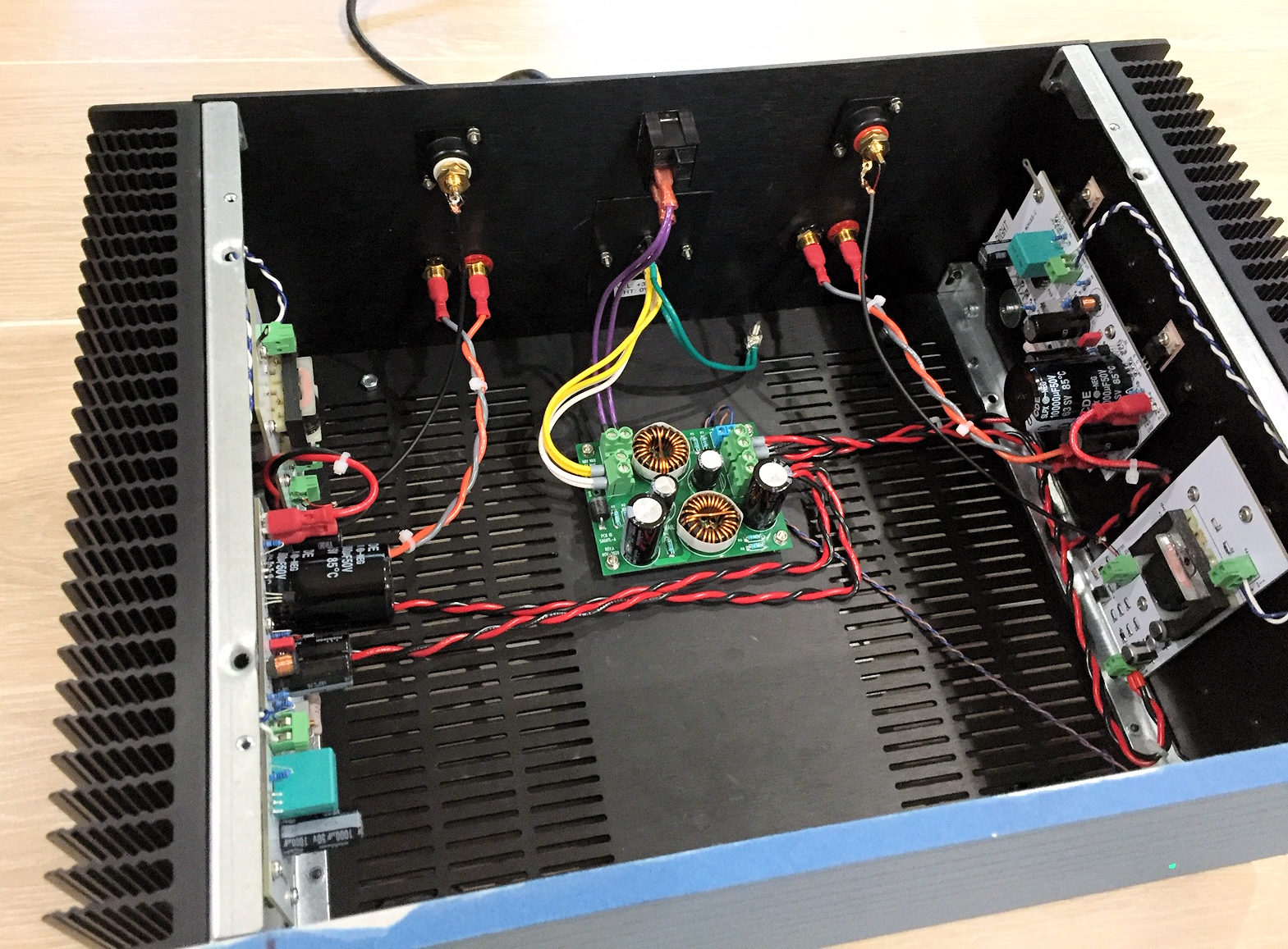
I'm still tinkering with an experimental higher-than-3-ampere SMPS filter board (below), but it is NOT ready for public release and I have no estimated timetable. Who knows, it might not work well and I might decide to throw it in the trash. Hold not your breath. Get not your hopes up. Blessed is he who expects nothing, for he shall never be disappointed.
A few members have mused about laying out a new PCB but using SMD components, however if there have been any announcements about Gerbers or boards or kits available, I myself haven't seen them.
I'm still tinkering with an experimental higher-than-3-ampere SMPS filter board (below), but it is NOT ready for public release and I have no estimated timetable. Who knows, it might not work well and I might decide to throw it in the trash. Hold not your breath. Get not your hopes up. Blessed is he who expects nothing, for he shall never be disappointed.
BinAB, please feel free to modify the circuit design & component values, however you like -- but you now own the responsibility for analyzing its safety and performance. Including the RF performance of the PCB layout. I recommend you wear safety goggles and gloves the first time you power it up and connect it to a dummy load.
_
_
Last edited:
Hi Mark,
Thanks as usual for all your hard work. Is a Rev. B. coming? The reason I ask is the store is out of the boards and was just wondering if they are coming back.
Cheers,
Greg
I will be shipping a new reload of the kits to the diystore this week. I've almost packed all of them.
--Tom
LTSpice is my friend here 😀 gotta make sure there's no ringing at least!BinAB, please feel free to modify the circuit design & component values, however you like -- but you now own the responsibility for analyzing its safety and performance. Including the RF performance of the PCB layout. I recommend you wear safety goggles and gloves the first time you power it up and connect it to a dummy load.

Sounds great. Music even more seems to come from nothing.Nice work, jaaptina! Hope you enjoy the sonic results.
Between 24V psu and NuTube inside a Purifi Eval1 amp. View attachment 968026
Looks sweet.
Enjoy the silence! 🙂
--Tom
I would like to use this filter after an smps that specifies a maximum of 330uF can be added at the output.
Not really understanding the details of the interaction between the resistors, inductors, and capacitors on this board, I am wondering how much capacitance the source to the board "sees" and if this filter meets that 330uF specification?
Not really understanding the details of the interaction between the resistors, inductors, and capacitors on this board, I am wondering how much capacitance the source to the board "sees" and if this filter meets that 330uF specification?
- Home
- Source & Line
- Analog Line Level
- PO89ZB, an inline DC filter for SMPS wall warts. Preamps, HPA, Korg NuTube, etc