I think any that is above your SMPS voltage should be ok, and pls note it's technically not a Zener:
Difference between TVS Diodes and Zener Diodes (1) | Toshiba Electronic Devices & Storage Corporation | Europe(EMEA)
I looked it up because it trigggered me, but that few lines are sufficient for me, I won't dig into it any further.
Thank you.
SMPS DC filter for RPi
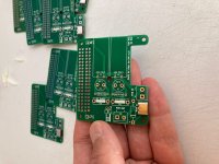
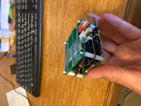
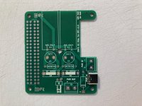
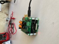
So the HAT boards I designed with Mark's SMPS inline DC filter circuit came in. I tested all 10 with a USB-C RPi power supply plugged in to the SMT receptacle and I can read 5.26V across the spot where the TVS goes, so the USB-C receptacles were mounted properly, though 4 of them are a bit crooked- just cosmetics. The two mounting spots for the 40-pin GPIO, one for direct-mount on top of a RPi, one for mounting on top of a HiFiBerry DAC or similar card in the lower position, look like they align as well (see the pictures). I'll be building up a couple and testing them with my RPi and sound cards over the next few weeks, time permitting, so I don't know yet if they actually work!
I have 7 of these bare boards to spare, to anyone looking to test and play with them. In the spirit of thanks to the diyaudio community, to Mark for designing and sharing this useful little filter with us, and to avdesignguru for encouraging me to teach myself KiCad and for reviewing the design, I offer these 7 for free to the first 7 people who pm me for them. I can even throw in a 40-pin header and a couple of jumpers if you'd like. For international folks, I ask that you consider reimbursing me for postage; for US folks I'll cover it.
Attachments
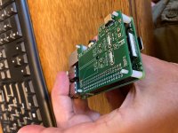


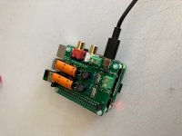
Lovely 3D arrangement! Congratulations. When the filter board is mounted atop the board with the two RCA jacks, one white and one red, it instantly becomes clear why there's a notch in your PCB. Please let us know how well it works when playing music.
Thanks, Mark! I didn't get as far as music today on account of some unresolved library file issues, but I did get through power up. I didn't see any under-voltage lightning bolts from the Pi (4.6V or so); the lowest I measured across the output with a cheap DMM was 5.05V, so hooray. Across the first current sense resistor which sees 5.26V I measured voltage drops of 25mV at idle (625mA I guess), up to 54mV (1.35A) under disk copying, so well under the 3A rating of the circuit and the wall wart. Also hooray.
Attachments
Hello everyone, on diyAudio Store the Kit is finished, do you know if it will be available again?
Split Rail vs CT Transformer
I built a bipolar version of this filter and put it downstream of a Mean Well NSD15-48D15 15 watt DC-DC regulated dual output converter to create a filtered +15/-15V SMPS supply. This was for a headphone amplifier I had recently built. The Mean Well converter accepts 18 - 72VDC so I used a Mean Well GST25U24-P1J 24VDC 1A single output SMPS that I had on the shelf.
It ended up sounding better than the 20 watt regulated bipolar linear power supply that I had been using. Very tight and well defined in the bass but not "bass heavy". I wonder if this is because the converter might provide a better ground reference? Better than a dual secondary or center tapped transformer design? Also I noticed enhanced clarity across the entire audio range with no loss of smoothness in the sound. This I attribute to the noise filters.
Thank you, Mark, for sharing this excellent filter design.
Hi Avdesignguru,
Nice bipolar filter layout 😉
Did you also have a pcb made for the MeanWell NSD15-48D15?
Nice bipolar filter layout 😉
Did you also have a pcb made for the MeanWell NSD15-48D15?
Congratulations, @avdesignguru! I am delighted that your dual filter worked so well, and noticeably improved the sound of your gear. I hope you included the TVS protection diodes on your board, since in a bipolar supply + bipolar filter there are so many ways to make a wrong connection. You don't want to explode a capacitor (or a Mean Well converter module) during setup!
I'm currently listening to an outboard converter connected to my dual filter PCB which includes the TVS diodes. The attached schematic and board design is in production, soon to be on its way to me.
Unfortunately, the Mean Well NSD15-48D15 is in a very low stock situation at Mouser and is currently non-stock at DigiKey. There is a Phoenix, USA distributor that I have not used, onlinecomponents.com, that shows qty=55 in stock. Perhaps this product is just too new to be popular yet, as the spec sheet is dated 10/20/2020.
Unfortunately, the Mean Well NSD15-48D15 is in a very low stock situation at Mouser and is currently non-stock at DigiKey. There is a Phoenix, USA distributor that I have not used, onlinecomponents.com, that shows qty=55 in stock. Perhaps this product is just too new to be popular yet, as the spec sheet is dated 10/20/2020.
Attachments
Question for Mark
Do you think I could/should add a TVS diode across the power jack input to the DC-DC converter to prevent someone plugging in a reverse wired wall wart supply and accidentally damaging the converter? Does the attached look correct? Am I correct in assuming the TVS does not load the supply in any way unless the input to it is reverse wired or exceeds 68V?
Oh, and the input should probably be labeled something like 18-48VDC, not 18-72VDC, correct? In the USA at least, you probably won't find a wall wart above 48VDC.
Attachments
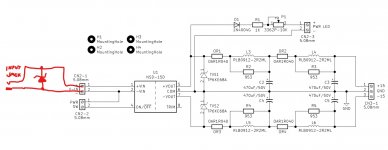
Yes, 48V seems to be about the highest. I'd definitely include a unidirectional TVS, a big ole bohunker 5000 watt device in a R-6 or P600 package with mongo hefty leadwires. Here's an example for just under two dollars: Digikey link
I have 5 of these boards left if anyone else is interested.
Now down to two.
Hi Mark,
Thanks for the TVS link, always interesting...
I am not familiar with the big Mean Well SMPS and don't know if they include some kind of protection should they fail. In short, I want to make sure my VFET will be protected if the SMPS fails and nothing like 230V or whatever bad may happen / could destroy the nonobtanium output transistors.
In your experience, could it make sense to add such a TVS at the power input in case the SMPS (or else) fails? Or are in fact these devices already protected / include similar inside?
What would be your recommandation?
Many thanks for your help
Claude
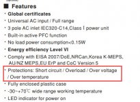
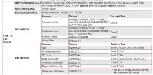
On most modern AC/DC SMPS, there is a lot of protection. The input can whistand the "normal" transient on an AC line (input is 85-265Vac) + abnormal transient such those defined in IEC 61000-4-5 (a TVS is used to pass the IEC 61000-4-5 test)
Attachments
Sorry, you'll need to find someone else to engineer a total protection solution for you. That's an area in which I have zero experience and zero knowledge. Maybe Nelson Pass can recommend a consultant whose hourly fees are not astronomical.
_
_
Fair enough, thanks Mark...
Kartapus, yes, they all have that, question is how do they do that. Failsafe mode is my worry. SMPS die quite abruptly on my computers, only place where they are regulary used. When on laptops, no problem, but then perhaps because of protections and battery. On stationary units, let's say the protections were OK when all was working, not when the SMPS itself failed woith age, with sometimes disastrous consequences beyond the SMPS. Not sure it is representative, I lack experience...
Anyway, it is perhaps time I get my hands and mind dirty and dig into all that
Thanks for the replies
Claude
Please let us know how well it works when playing music.
So, after extensive listening with two different Pi/DAC HAT combinations, I don't hear any obvious improvement when the DC filters are in use. If anything, there may be a slight reduction in dynamic range when they are, but I could be hallucinating. Setups are:
Raspberry Pi 2 Model B Rev 1.1, AD1868 based R-2R DAC HAT (audiophilediyer.com)
Raspberry Pi 3 Model B REv 1.2, HiFiBerry DAC2 HD
There's a rhythmic pop-hiss from the AD1868 card that isn't helped by the DC filter HAT. That said I personally prefer the sound of this card over the DAC2 HD, at least for the rock/pop/"girl and guitar" type music I typically listen to.
Attachments

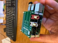
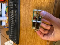
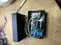
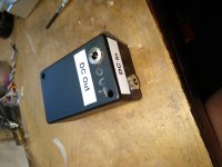
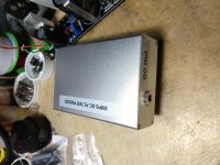
My two enclosure designs
Both cases were ordered from Amazon.
The black plastic case is: DGZZI Electrical Junction Box 4PCS Electric Plastic Black Waterproof Project Junction Case 3.15x1.97x1.38 inches(80x50x35mm; $8.60 for 4 boxes) while the silver aluminum box is: Eightwood Aluminum Box Electronic Amplifier Project Enclosure PCB Circuit Board DIY Case, 4.32 x 2.82 x 1.13 inch (LWH); $11.00. Little soft plastic feet stuck on underneath.
Thanks for the board design & kit sales!
Attachments

There's a rhythmic pop-hiss from the AD1868 card that isn't helped by the DC filter HAT.
Bummer. I've heard that same sound and was hoping this might help. Maybe I'll get lucky, though.
- Home
- Source & Line
- Analog Line Level
- PO89ZB, an inline DC filter for SMPS wall warts. Preamps, HPA, Korg NuTube, etc