Just have a look at your power brick from the Laptop, I am pretty sure you are exceeding 3A....
That said why would the laptop be in charge when using it to play music ? If I was doing what you are doing I would listen with the charger disconnected ?
Or do you use the laptop brick to power another device like Preamp ?
Sorry for the confusion...
That said why would the laptop be in charge when using it to play music ? If I was doing what you are doing I would listen with the charger disconnected ?
Or do you use the laptop brick to power another device like Preamp ?
Sorry for the confusion...

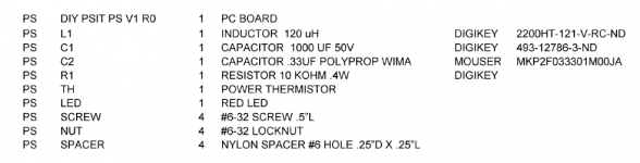
If you are a self-sufficient, brave, confident, and experienced DIY builder, you could use the SMPS filter design which Nelson Pass created for his DIY VFET project. That project draws a total of about 4 amps from the SMPS, and his filter circuit design specifies a Bourns inductor which is rated for 5 amps.
You'd either lay out your own PCB for it, or else build the circuit on vectorboard with beefy point to point wiring.
_
You'd either lay out your own PCB for it, or else build the circuit on vectorboard with beefy point to point wiring.
_
Attachments

I am going out on a limb here but the filter has no inherent sound quality. I am using five currently and all they do is allow less noise to reach the audio device via the DC power connection. Any change in perceived sound quality for a connected device is only due to a lower noise floor on the power supply. It is curious that the filter has created negative changes to the sound quality of the audio output of your laptop.
Merlin,
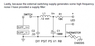
Mark kindly hinted you towards a possible and simple solution. It is obviously inspirational and you really need to know what you are doing before getting started. I guess under load you mean output of the filter, and if so it isn't the LED, but is rather around C1 (so +V output is not quite where you believe.)
LED, R1 and thermistor are obviously not required if just "thinking simple filter" block.
I hope this helps
Claude
Oh, and the input protection Zener diode Mark used in his filter seems like a good idea to me...
I think any that is above your SMPS voltage should be ok, and pls note it's technically not a Zener:
Difference between TVS Diodes and Zener Diodes (1) | Toshiba Electronic Devices & Storage Corporation | Europe(EMEA)
I looked it up because it trigggered me, but that few lines are sufficient for me, I won't dig into it any further.
Difference between TVS Diodes and Zener Diodes (1) | Toshiba Electronic Devices & Storage Corporation | Europe(EMEA)
I looked it up because it trigggered me, but that few lines are sufficient for me, I won't dig into it any further.
Yep, of course, should have looked before posting out of my head... but you got the idea of input protection
Thanks for the correction
Claude
Thanks for the correction
Claude
Claude, I had to look it up myself, I am certainly in no position to teach anyone anything, at least not it EE .... 😀

- Home
- Source & Line
- Analog Line Level
- PO89ZB, an inline DC filter for SMPS wall warts. Preamps, HPA, Korg NuTube, etc