Claude, I will use 6A EMI filters per group as my devices are all low power but I have a few types to try out. Absolute most rewarding however is the use of a 150 VA medical isolation transformer for my sources. This will be connected to one of the Schüko groups and it will feed my sources. I want to get rid of it but when I disconnect it I immediately regret that as it has most impact of all measures in my setup.
Mains filters were kind of unnecessary in the past but this has changed due to SMPS, LED lighting, wireless, bluetooth, cell phone networks and other RF polluters. In 2021 one does not get away with plastic or wooden casings anymore because of that. I experimented with PS Audio units (crappy as these die and I repaired quite a few) and various other types. They have a positive influence certainly when switchers are used that might be polished with an output filter but pollute the mains side way more than linear PSU's do. So in effect switchers should be filtered carefully at both DC and AC sides. Most SMPS are black boxes that are RF/noise generators (some also radiating!) at both sides and need double filtering, hence my choice to go all linear (still I regularly polish SMPS for others) which don't require either as much. It is however impossible to ban all SMPS as these are standard with routers, switches etc. For this I measured and tested for many years now and it is useful to filter per device instead of just 1 filter for all. A mains voltage analyzer proves directly what improvements are made. It leaves me stupefied that SMPS are so pushed as these really need to be of very good quality to compete in low power and then they are more expensive than a DIY LPS.
I could open a thread about the Netzverteiler but it seems trivial to build one to me although the widespread use of wall warts in audio nowadays makes me think mains cabling is not for everyone. For now I think I spammed this thread already too much.
PS with a new house it is a good thing to have a separate group with 2 x 2.5 mm2 cables in parallel to the audio wall sockets. PE is required by all means.
Last edited:
Ah, sorry, it is first of of course Conrad and not Konrad
Now the filter is from the 80's and was at least produced until the current millenium, but wasn't visible on their website anymore by then unless searching deeply.
Part N. is 0190 179
Given the Schaffner parts and the big size of this kit, perhaps they withdrew it?
Now the filter is from the 80's and was at least produced until the current millenium, but wasn't visible on their website anymore by then unless searching deeply.
Part N. is 0190 179
Given the Schaffner parts and the big size of this kit, perhaps they withdrew it?
I can't find it anymore :-(
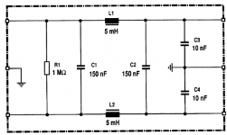
Here is its schematic. From memory the caps are WIMA MKS. Filter is OK for 50 Hz 230V/6A, Fc is 1.7kHz and slope only 6dB/oct. Loss / CC resistance through the filter is R=0.25. Depending on how you connect it, it can filters both directions if you bother with earth/ ground.
It may inspire some so although not the topic here. I won't post more on that to avoid polluting Mark's excellent thread, but "while at it", it could always be nice to have an expert view (Mark's of course 🙂.
May that be useful - worked great on most gears, never affected the sound negatively (which is not always the case with main's filters) but sometimes didn't bring any change (obviously USB PS, SMPS).
Stupid me never tried it at the output of an SMPS: although not designed with HF filtering in mind, who knows...
Claude
Attachments
Last post about the subject but you should bother with PE otherwise it won't filter adequately. It is meant to filter HF/RF at 230V AC mains side and does so partly to PE. Also ANY device that has a 3 prong IEC inlet requires PE either for safety and/or for mains filters built internally.
PE and audiophiles is opening a can of worms. Many use 3 prong IEC devices on wall outlets without PE and wonder why they get a tickling feeling when they touch the device 😀 The internal mains filter won't be able to filter properly as well. Sheer incompetence if you ask me certainly when one is worried about the tiniest details. Absolute worst is to connect audio GND to chassis instead of PE (common practice in some circles) when PE is available like it should be AND using a 3 prong IEC inlet but then no wire to the PE pin. Seeing that makes one contemplate what thinking pattern was used 🙂
PE and audiophiles is opening a can of worms. Many use 3 prong IEC devices on wall outlets without PE and wonder why they get a tickling feeling when they touch the device 😀 The internal mains filter won't be able to filter properly as well. Sheer incompetence if you ask me certainly when one is worried about the tiniest details. Absolute worst is to connect audio GND to chassis instead of PE (common practice in some circles) when PE is available like it should be AND using a 3 prong IEC inlet but then no wire to the PE pin. Seeing that makes one contemplate what thinking pattern was used 🙂
Last edited:
Many thanks Jean-Paul!
Claude
PS: my bad, total Rcc= 2.2R, not 0.25R as posted, wrong head calculation
Claude
PS: my bad, total Rcc= 2.2R, not 0.25R as posted, wrong head calculation
Last edited:
I'll try to remember to post this link from time to time. It's just exactly what many PO89ZB builders need to see:
diyAudio post #4371
It can be done. YOU can do it! Victory is yours.
diyAudio post #4371
It can be done. YOU can do it! Victory is yours.
Hi, everyone. Just a reminder that I have quite a few boards here, ready to send out. If you want one or two and are in the US, then they are free. If you want more than two or are not in the US, then I'll ask you to toss me a couple bucks to cover the costs (60 cents per board) and shipping (usually just a first class letter, though more than three boards takes it over an ounce). PM me if you want some.
Note also: Mouser BOM here for one click ordering. This does not include DC jacks, etc, as on the original BOM.
Note also: Mouser BOM here for one click ordering. This does not include DC jacks, etc, as on the original BOM.
I put together my 3 stage filter breadboard, but now I realize my old oscilloscope is not stable enough for good measurements, so I ordered a new scope, so it can be re-measured next week.

The cheap SMPS is 5A 32V, with Zout ~ 170 mohm

The cheap SMPS is 5A 32V, with Zout ~ 170 mohm
Last edited:
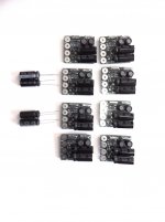
Mark's Filter Imperial Troops are all GO 🙂
Ready to join their metalic starbase(s)
Have fun
Claude
PS: note the 4 extra caps in case I am not too lazy to upgrade some original filters to the latest spec
Thunderbirds are Go! 04 Thunderbirds Terror In New York City - YouTube
Well spotted Mello 4!
The GO was indeed a hint to the Thunderbirds... I still like watching with my kids (memories...)
The GO was indeed a hint to the Thunderbirds... I still like watching with my kids (memories...)
PO89ZB is a Low Pass Filter. It rejects high frequency noise created by the Switch Mode Power Supply, while allowing "low frequency" signals (like zero Hertz DC !) to flow unimpeded. You want to learn more about LC Low Pass Filters.
I think these three Youtube videos look very approachable. Spend an hour watching the three of them and see what you think.
1. (easiest) Stan Gibilisco video
2. techgurukula video
3. (slowly works through an example) Chris's Workbench
Those were very helpful. Where were they all my life?! 🙂
--Tom
Hi guys,
Maybe a silly question:
I'm planning to put one (or two) of these filters into my newest build (Arylic wifi source board, Dayton DSPB-250 Dayton Audio - DSPB-250 2x50W Class D Audio Amplifier Board with DSP, and KAB-100M Dayton Audio - KAB-100M 1x100W Class D Audio Amplifier Board with Bluetooth 4.0.
I think I need to use 2 of the PO89ZB boards in parallel to smooth out any nasties in my meanwell GST120A24-P1M 24v 5A supply Blocked
The question is, provided that I can fit them in the enclosure, would it be defeating the purpose to put the filters into the same enclosure with the amps and source boards?
I'd really rather not have a big power brick with a train of tumors leading up to the amp box, but if the 1 meter of cable between the SMPS and the filters has a significant impact, then I'll put up with it.
Thanks!
Putting the filter in the same enclosure is not a problem.
However, before putting 2 of these filters in parallel to cope with the current flow you are dealing with, I would suggest you wait for Mark's latest filter as that one may exactly match your needs (6A SMPS filter for power amps).
Mark hinted to that filter in this thread, it is currently being tested...
I hope this helps
Claude
I myself would NOT attempt to connect two PO89ZB filter boards in parallel, Brian. They won't share current equally and the one that conducts the greater current could easily catch fire, which you do not want.
There's a high current filter schematic someplace on this thread, whose designer claims it should work at 5 amps. If you trust their opinion and if you feel lucky, you could try that. You might have to lay out your own PCB and arrange for its fabrication.
Don't expect any high current filters from me anytime soon; my attempt at a 6 amp filter might fail -- failures do happen -- and it's not being pursued with any great urgency. If you decide to wait for it, I warn you: your wait might last many months. Or it may turn out to have irredeemable, fatal weaknesses, and NEVER emerge. Failures do happen.
Haha. Ok then! I appreciate the caution of a good EE. Reminds me of my friends back east who cut their teeth on spy satellite hardware. 🙂. Talk about a high price for failure...
Here’s another option: i have 2 amps, each expected to draw max 2A or so. What if i split the 24v rail and use one filter for each branch? Would they interact in an undesirable/unpredictable way? I know that alot of this filtering is based on preventing resonance between the switching and everything else down the line so it may not be a straightforward solution.
Perhaps a naive question, but how can I actually calculate/reliably measure the peak current draw of an amp? I typically just add some headroom to whatever a spec sheet says, but in this case, i won’t be running either of these amps anywhere near high gain.
I have access to a number of 100W 8 ohm power resistors but I didn’t think they were an absolutely representative stand-in for a driver.
Thanks!
Well spotted Mello 4!
The GO was indeed a hint to the Thunderbirds... I still like watching with my kids (memories...)
I still enjoy watching it... Supermarionation from 1965. Those guys were great artists and craftsman.
I myself would NOT attempt to connect two PO89ZB filter boards in parallel, Brian. They won't share current equally and the one that conducts the greater current could easily catch fire, which you do not want.
There's a high current filter schematic someplace on this thread, whose designer claims it should work at 5 amps. If you trust their opinion and if you feel lucky, you could try that. You might have to lay out your own PCB and arrange for its fabrication....
I need to measure my breadboard next week to verify, before an etched PCB is created. I may need to rework it.
In in order to use two 3A boards in parallel for 5A application one would need a dominant ballast resistance in series with each filter to make them share current, but that would be an extra voltage drop from the supply & not the most efficient solution.
Last edited:
Quote: "i have 2 amps, each expected to draw max 2A or so. What if i split the 24v rail and use one filter for each branch?
I am not sure I am unerstanding what you are saying, but I have 1 set up for bi amping where a single high power SMPS powers 2 power amps. In front of each power amp sits a filter. Makes: 1 SMPS - 2 x PS outputs with cables - 2x "Filter + amp".
Works great
This is of course very different from running 2 filters in parallel as in the latter case they would "join" again to power the same unique device.
I am NOT running filters in parallel and prefered to use other filters in the one application where 6A each were needed...
Claude
Last edited:
- Home
- Source & Line
- Analog Line Level
- PO89ZB, an inline DC filter for SMPS wall warts. Preamps, HPA, Korg NuTube, etc