Link for PDF says "Forbidden"
Don't know why. The PDF file is too big for upload here.
Try Google "Arthur Bailey transmission line 1972" to find it. It works that way.
No. In the 1972 text ( http://www.t-linespeakers.org/download/Bailey_TLs_2.pdf ) at the first page, end of the first column and beginning of the second column, Bailey wrote:In summary, what Beiley and Bradbury said was that they could make a physically 1/4 wave tube into a 1/2 wave tube by stuffing it with 1/2 lb/cuft of long fiber wool. They had analysis and test to prove that.
"The effect of wool filling in the pipe is to slow down the wave relative to its velocity in free air. This reduction factor is between 0.7 and 0.8 for the recommended packing density..."
To make a 1/4 wave tube into a 1/2 wave tube requires speed reduction factor 0.5 - very far from 0.7 factor Bailey achieved.
Last edited:
The speed of sound will be slowed to some extent because the additional thermal mass will move the expansion/compression of the air by the sound wave from a largely adiabatic one towards a more isothermal one. A change to fully isothermal would give a maximum reduction of sqrt(1/1.4) = 0.845 an amount that seems rather unlikely to me for a line lightly stuffed with wool. Did he give an explanation for this large reduction?"The effect of wool filling in the pipe is to slow down the wave relative to its velocity in free air. This reduction factor is between 0.7 and 0.8 for the recommended packing density..."
No, of course he did not!
My edit on my previous post somehow don't catch the word "supposedly". I (intended) to write "very far from 0.7 factor Bailey supposedly achieved".
If my memory serves me well, I think Augspurger wrote that maximum reduction is about 0.8.
My edit on my previous post somehow don't catch the word "supposedly". I (intended) to write "very far from 0.7 factor Bailey supposedly achieved".
If my memory serves me well, I think Augspurger wrote that maximum reduction is about 0.8.
Unless about 0.8 is 0.845 this is again a larger reduction than I would expect. Measurements show heavily stuffed sealed box may realize over 50% of the theoretical maximum benefit from changing the compression/expansion process (lowering of resonant frequency) but a transmission line has lighter stuffing. It seems hard to believe the speed of sound is going to change by more than a few percent in a typical transmission line speaker.If my memory serves me well, I think Augspurger wrote that maximum reduction is about 0.8.
In Mr D'appolito's book "testing loudspeakers" on page 137 he shows measurements of 76% reduction in the speed of sound in a TL and claims 71% as the theoretical minimum.
Trolling a bit here and found much great discussion on TL's.
However, I wonder about the OP's concern about that 50 hz null. It's occurring in the natural roll off of the speaker and at a point that's already 15 dB down from the speaker's normal output. Granted, the null dips an additional 15 dB down, but only briefly. It also seems to me (from the OP) to have been discovered during measurements.
Thus, the question arises in my mind, is it really audible during normal, dynamic music playing?? If not, all the subsequent discussion seems to be much ado about almost nothing.
Hmmm. I had a think and a quick browse of the internet. Only considering the stiffness of the air alone as I was doing above is insufficient. For example, if the porous material moves to some extent with the sound then that is increasing the effective mass which will slow the propagation speed. I haven't found a reasonable reference the internet will let me read and so I may have to go to a library but I am now pretty confident that the speed of sound can be greatly reduced in heavy stuffing. Of course, a transmission line doesn't want heavy stuffing but my stated minimum of 0.845 based on just the air following a polytropic process does not hold.In Mr D'appolito's book "testing loudspeakers" on page 137 he shows measurements of 76% reduction in the speed of sound in a TL and claims 71% as the theoretical minimum.
Bailey's theory that the long fiber wool moved and created an additional effect that slows down the speed of sound has been questioned. Not saying that theory is correct or not, but it led to two questionable assumptions by others that continue; only long fiber wool can do that, and if you stuff the line heavily enough, it only needs to be half as long.
Paul
Paul
Hmmm. I had a think and a quick browse of the internet. Only considering the stiffness of the air alone as I was doing above is insufficient. For example, if the porous material moves to some extent with the sound then that is increasing the effective mass which will slow the propagation speed. I haven't found a reasonable reference the internet will let me read and so I may have to go to a library but I am now pretty confident that the speed of sound can be greatly reduced in heavy stuffing. Of course, a transmission line doesn't want heavy stuffing but my stated minimum of 0.845 based on just the air following a polytropic process does not hold.
Last edited:
I tried to look up the topic in the scientific literature not a hobbyist publication and so I am pretty confident that the speed of sound in porous media can be a lot slower than in air alone. What gives confidence is reasoning why the speed has changed rather than simple statements that it has. Physical models based on that reasoning that predict measurements reasonably well adds to the confidence.Bailey's theory that the long fiber wool moved and created an additional effect that slows down the speed of sound has been questioned. Not saying that theory is correct or not, but it led to two questionable assumptions by others that continue; only long fiber wool can do that, and if you stuff the line heavily enough, it only needs to be half as long.
Paul
If you heavily stuff a transmission line a negligible amount of sound will reach the end making "tuning" the length somewhat irrelevant. The slowing of the speed sound does however seem to significantly affect the depth required by some sound absorption devices. The slowing of the effective speed sound shortens the wavelength and so devices that need to be quarter of a wavelength deep to work effectively can be less deep than one might initially expect.
The speed of sound will be slowed to some extent because the additional thermal mass will move the expansion/compression of the air by the sound wave from a largely adiabatic one towards a more isothermal one. A change to fully isothermal would give a maximum reduction of sqrt(1/1.4) = 0.845 an amount that seems rather unlikely to me for a line lightly stuffed with wool. Did he give an explanation for this large reduction?
It turns out that the changes attributed to the damping reducing the speed of sound (which is generally insignificant) is due to a line shrinking in cross-section towards the terminal. It has been shown mathematicaly (by bothMJK & Augspurger using 2 very different models) and empirically that a line tapered this way needs tobe shorter and that one the tapers the other way (ie Voigt) needs to be longer.
Not because of a change in the speed of sound.
We used this to purposely increase the line length to change a shortish ML-TL into a taller ML-V.
dave
There are two different, unrelated mechanisms:
1. Lowering the speed of the sound inside the pipe because of stuffing.
2. Lowering the resonant frequency of the pipe with tapering - works with or without stuffing.
1. Lowering the speed of the sound inside the pipe because of stuffing.
2. Lowering the resonant frequency of the pipe with tapering - works with or without stuffing.
The brochure says the exterior height is 400mm and TL length is 48in. As drawn above is not 400mm high and only about 40in TL length.
https://pmc-speakers.com/sites/default/files/attachments/TB1-Brochure.pdf
https://pmc-speakers.com/sites/default/files/attachments/TB1-Brochure.pdf
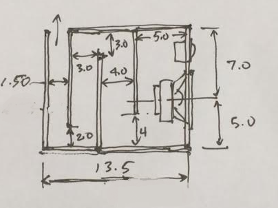
Your drawing is for PMC DB1 (height=290 mm). Height of PMC TB1 is 400 mm.Here is a drawing extracted from a PMC extents drawing to which i have added internal dimensions.
Test Case TL w/ DC130A-8
For fun, I designed a tapered TL with a 48in path (same as TB1) but made it with the following segment depths for each 12in traverse (4 total for 48in): 5in, 4in, 3in, 1.5in. Width is 6.0in (internal) and I designed it for the Dayton DC130A-8 driver. I will probably build it out of foam core and pair it with a DC28F-8 dome tweeter for a cute little 2-way TL monitor. The driver is located 7in down from the closed end, and the vent is up firing at the back. Here is a sketch of the design:
I modeled this in Akabak with 180 deg hairpin turns represented with the usual four 90 deg turn segments (expansion/contraction/expansion/contraction). There is stuffing in the closed end down to where the first turn is. However, I am doing two cases where I can add stuffing or not for the last straight segment (10in long) up to the vent. Adding resistive flow here has a large impact on frequency response, electrical impedance, and cone excursion as we will see.
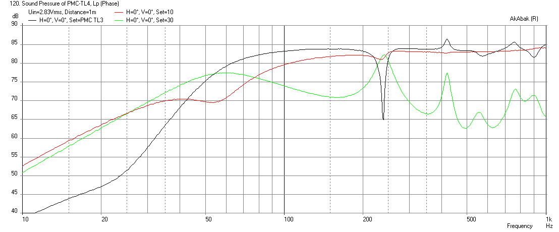
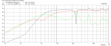
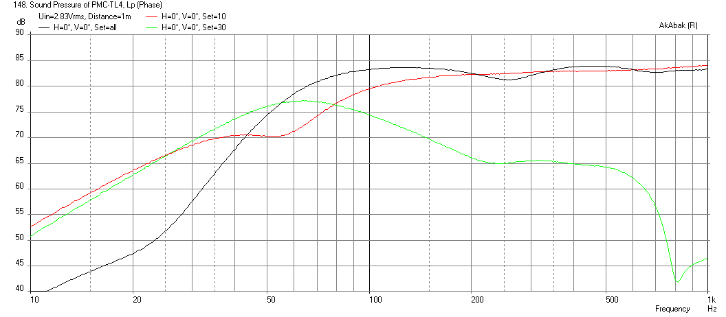
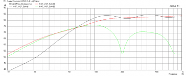
Here is the predicted frequency response at 2.83v and 1m for the unstuffed and stuffed case, respectively:

With Stuffing:
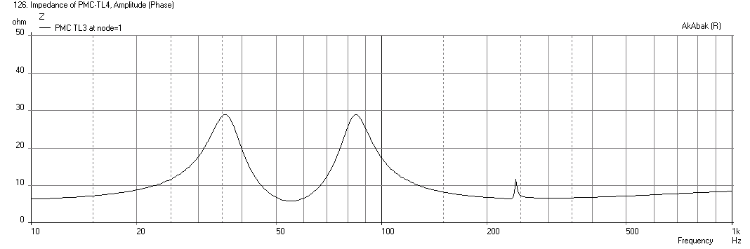
Here is the predicted impedance for the unstuffed case (max is 29 ohms):
With Stuffing (max is 20 ohms):

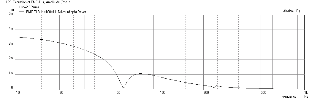
Here is the predicted cone excursion for the unstuffed case:
With Stuffing, the motion null at fb goes away:
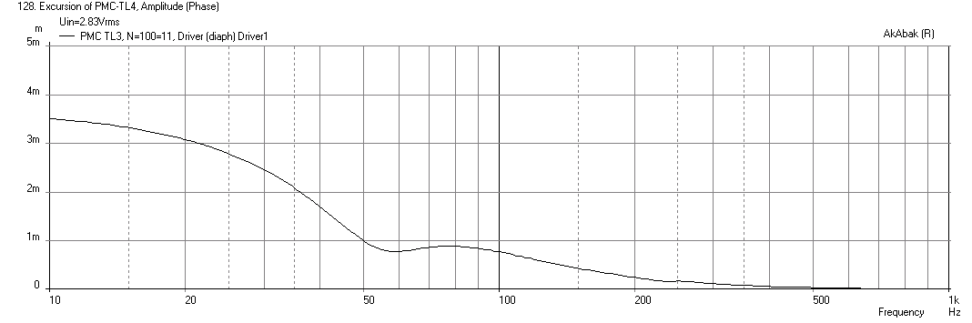
As we can see, the addition of some dense stuffing just to the last segment can really remove the sharp 24dB/oct fall-off and give it a more gradual slope, at the expense of SPL at the low corner. The impedance peaks are flattened somewhat, and the cone excursion is smoothed out so it doesn't go through a motion null at the tuning frequency (possibly keeping the cone moving to cool the voice coil for low notes). The TL tuning frequency fb was about 55Hz and remains the same with or without stuffing.
Stuffing in Akabak is set in "waveguide" elements by specifying the equivalent resistive pressure loss due to flow in Pa sec/m^3.
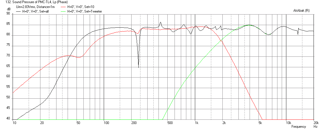
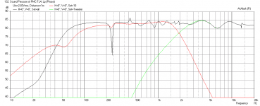
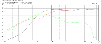
And here is what the predicted response looks like with the tweeter and a 4th order BW LPF and 2nd order Bessel HPF XO at about 2kHz.
For fun, I designed a tapered TL with a 48in path (same as TB1) but made it with the following segment depths for each 12in traverse (4 total for 48in): 5in, 4in, 3in, 1.5in. Width is 6.0in (internal) and I designed it for the Dayton DC130A-8 driver. I will probably build it out of foam core and pair it with a DC28F-8 dome tweeter for a cute little 2-way TL monitor. The driver is located 7in down from the closed end, and the vent is up firing at the back. Here is a sketch of the design:
I modeled this in Akabak with 180 deg hairpin turns represented with the usual four 90 deg turn segments (expansion/contraction/expansion/contraction). There is stuffing in the closed end down to where the first turn is. However, I am doing two cases where I can add stuffing or not for the last straight segment (10in long) up to the vent. Adding resistive flow here has a large impact on frequency response, electrical impedance, and cone excursion as we will see.
Here is the predicted frequency response at 2.83v and 1m for the unstuffed and stuffed case, respectively:
With Stuffing:
Here is the predicted impedance for the unstuffed case (max is 29 ohms):
With Stuffing (max is 20 ohms):
Here is the predicted cone excursion for the unstuffed case:
With Stuffing, the motion null at fb goes away:
As we can see, the addition of some dense stuffing just to the last segment can really remove the sharp 24dB/oct fall-off and give it a more gradual slope, at the expense of SPL at the low corner. The impedance peaks are flattened somewhat, and the cone excursion is smoothed out so it doesn't go through a motion null at the tuning frequency (possibly keeping the cone moving to cool the voice coil for low notes). The TL tuning frequency fb was about 55Hz and remains the same with or without stuffing.
Stuffing in Akabak is set in "waveguide" elements by specifying the equivalent resistive pressure loss due to flow in Pa sec/m^3.
And here is what the predicted response looks like with the tweeter and a 4th order BW LPF and 2nd order Bessel HPF XO at about 2kHz.
Attachments
-
 PMC-TL4-DC130A-8-Excursion-with-stuffing.png7.6 KB · Views: 548
 -
 PMC-TL4-DC130A-8-Excursion-no-stuffing.png7.3 KB · Views: 10,481
 -
 PMC-TL4-DC130A-8-Impedance-with-stuffing.png7.1 KB · Views: 10,635
 -
 PMC-TL4-DC130A-8-Impedance-no-stuffing.png7.4 KB · Views: 11,188
 -
 PMC-TL4-DC130A-8-Freq-with-stuffing.png15.6 KB · Views: 553
 -
 PMC-TL4-DC130A-8-Freq-no-stuffing.png30.6 KB · Views: 11,622
 -
 PMC-TL4-DC130A-8-Plan.png102.5 KB · Views: 12,681
 -
 PMC-TL4-DC130A-8-with-Tweeter-Freq.png35 KB · Views: 535
Last edited:
Why is the simulated stuffing only affecting the amplitude of the first and second resonances but not the higher ones. I would expect stuffing to be more effective at higher frequencies.I modeled this in Akabak with 180 deg hairpin turns represented with the usual four 90 deg turn segments (expansion/contraction/expansion/contraction). There is stuffing in the closed end down to where the first turn is. However, I am doing two cases where I can add stuffing or not for the last straight segment (10in long) up to the vent. Adding resistive flow here has a large impact on frequency response, electrical impedance, and cone excursion as we will see.
The equal magnitude of the output from the port and driver looks like a problem at the second resonance. Presumably more stuffing is needed to pull it down further?
Why have you chosen not to lightly stuff most of the line?
Why is the simulated stuffing only affecting the amplitude of the first and second resonances but not the higher ones. I would expect stuffing to be more effective at higher frequencies.
The equal magnitude of the output from the port and driver looks like a problem at the second resonance. Presumably more stuffing is needed to pull it down further?
Why have you chosen not to lightly stuff most of the line?
Yes, more stuffing can be added easily - it's just a starting point. Typically, the damping will be enough that the second peak doesn't show up. I can add more segments with light or moderate stuffing to see...
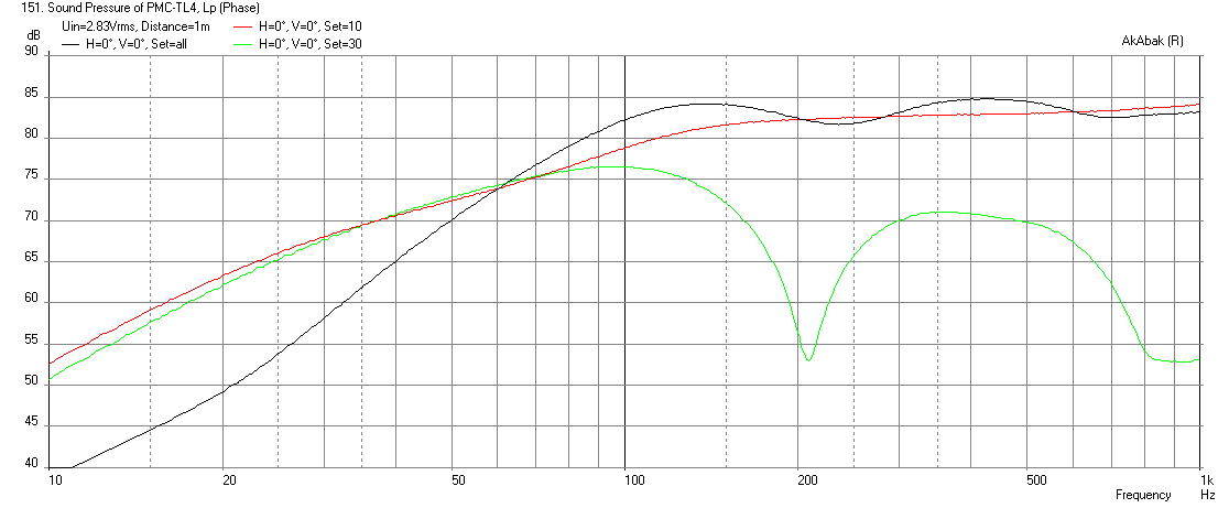
Effect of stuffing entire TL
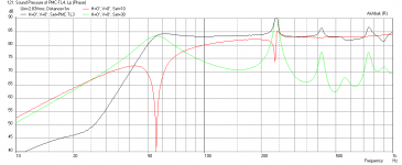
If I apply moderate stuffing along the whole line and light stuffing on the last segment, we get much less 2nd resonance peak:
If I exchange light stuffing for dense stuffing on the last segment (essentially plugging it up to reduce bass output from port and tending towards and aperiodic vent) - much like what PMC did, the response now looks a lot more like the measured response for TB1, with falloff starting around 90Hz. This smooths things out even more:
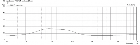
Here is corresponding impedance (single peak - aperiodic TL):

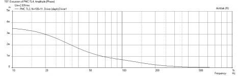
And corresponding cone displacement:

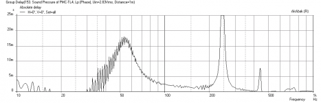
But the most remarkable improvement (at the expense of bass extension) is the reduced group delay, which is now around 4ms at fb (60Hz):
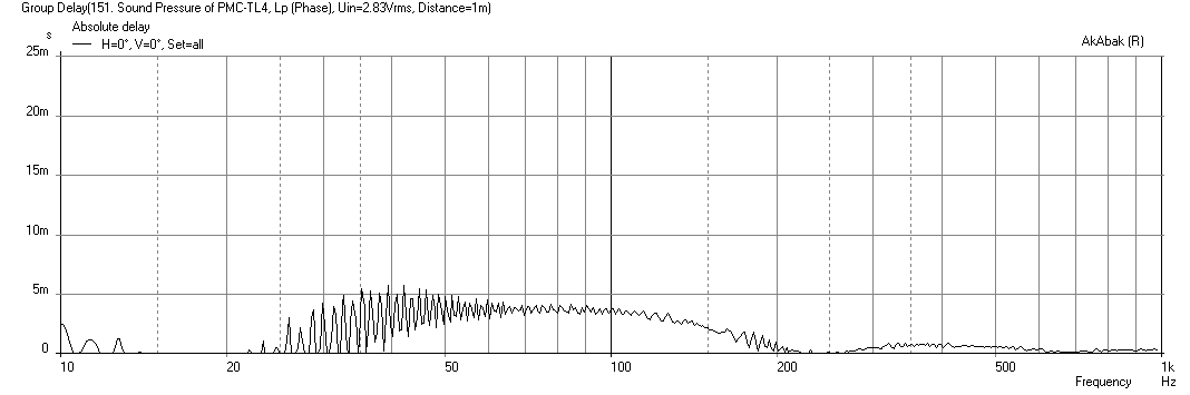
Compare this with the group delay for a TL that is only stuffed in the section from closed end up to just the first turn (as is usually done to effect max bass extension and bass SPL) - about 17ms:

So for a studio monitor where accurate timing of bass kick drum is desired, the tightly stuffed last segment seems ideal, although there is a lot less 50Hz kick drum to hear (70dB vs 74dB for lightly stuffed terminus, vs 81dB for no stuffing except for first segment).
Isn't this a lot more informative than arguing about Bailey's paper vs whatever?
If I apply moderate stuffing along the whole line and light stuffing on the last segment, we get much less 2nd resonance peak:
If I exchange light stuffing for dense stuffing on the last segment (essentially plugging it up to reduce bass output from port and tending towards and aperiodic vent) - much like what PMC did, the response now looks a lot more like the measured response for TB1, with falloff starting around 90Hz. This smooths things out even more:
Here is corresponding impedance (single peak - aperiodic TL):
And corresponding cone displacement:
But the most remarkable improvement (at the expense of bass extension) is the reduced group delay, which is now around 4ms at fb (60Hz):
Compare this with the group delay for a TL that is only stuffed in the section from closed end up to just the first turn (as is usually done to effect max bass extension and bass SPL) - about 17ms:
So for a studio monitor where accurate timing of bass kick drum is desired, the tightly stuffed last segment seems ideal, although there is a lot less 50Hz kick drum to hear (70dB vs 74dB for lightly stuffed terminus, vs 81dB for no stuffing except for first segment).
Isn't this a lot more informative than arguing about Bailey's paper vs whatever?
Attachments
-
 PMC-TL4-DC130A-8-with-all-stuffing-tight-at-terminus-GD.png8.8 KB · Views: 11,214
 -
 PMC-TL4-DC130A-8-with-all-tight-stuffing-displ.png7 KB · Views: 10,451
 -
 PMC-TL4-DC130A-8-with-all-tight-stuffing-Impedance.png6.4 KB · Views: 10,481
 -
 PMC-TL4-DC130A-8-with-all-stuffing-tight-at-terminus-Freq.png14.6 KB · Views: 11,366
 -
 PMC-TL4-DC130A-8-with-all-stuffing-Freq.png14 KB · Views: 11,421
 -
 PMC-TL4-DC130A-8-with-all-no-stuffing-GD.png8.7 KB · Views: 10,822
Last edited:
- Status
- Not open for further replies.
- Home
- Loudspeakers
- Multi-Way
- PMC TL Stuffing