Seems to me that BlindMelon7 is just asking how fat a sock he should stick at the output of the line. None of you monkeys seem to have an answer. 😛
Why would you expect anyone of us and yourself do?
I suggested BlindMelon7 to contact PMC and try to restore the original foam (Post #3). There is no alternate suggestion to that yet. 😎
Last edited:
I think best would be to measure and slowly add stuffing/foam at port until you get rid of that dip. Nothing beats empirical real-time tuning.
Back to the first post and back to the basics.I've experimented with an RTA mic 6cm from the center of the woofer. I took 3 measurements, one without the foam, one with the original foam (which did very little in it's current form) and one with a rolled up tea towel stuffed in the port, quite loosely but enough that it's fairly sealed.

They sound much better stuffed, although I feel like they've lost some "life". Could anyone advise me on a better way of going about this?
Close mic measurement of the woofer reveal dip which comes from the resonant behavior of this TL, with resonant frequency of just over 50 Hz. You should measure output from the port and add together with the woofer output. After that, you should came with the total frequency response similar to the graphs in the posts 32, 41 and 44. Crap, that is.
What to do to improve the frequency response of the PMC TB1? Not much, I am afraid. Design of the TL in the PMC TB1 is wrong and you can't improve it, because dimension of the box (TL length and cross-area) are fixed. You may try to add a little more stuffing inside the TL (not at the port). Piece of foam at the port is an acoustically transparent open-cell foam and has nothing to do with the acoustical properties of the speaker - it is for protection only (kids love to put toys inside ports).
Wrong. Ported TL is 1/4 wave. See the excellent post from xrk971:In summary, what Beiley and Bradbury said was that they could make a physically 1/4 wave tube into a 1/2 wave tube by stuffing it with 1/2 lb/cuft of long fiber wool.
Don't get all wrapped up in degrees of phase - just look at the fluid mechanical boundary conditions. A closed end and the "no-slip" boundary condition says that velocity has to go to zero, hence it anchors one end of a 1/4-wave.
open end boundary conditions = 1/2 wave (e.g., flute), closed end - open end boundary conditions = 1/4 wave (e.g., clarinet) open end:
That is why a clarinet can play a note twice as low as an equivalent length flute.
A closed-closed pipe also has the same boundary conditions as an open-open TL, the sound just stays inside.
Wrong. Ported TL is 1/4 wave. See the excellent post from xrk971:
Unfortunately, the gentlemen Bailey and Bradbury were not around to argue with you anymore. But their theory and tests results are still around.
If you and xrk971 cannot follow the linear algebra mathematics that Bradbury presented and led to his half wavelength conclusion, it is impossible to argue. The whole point that Bailey and Bradbury made was that long fiber wool changes the acoustics of an air column. It is purely a theory of simple fluid dynamics that they proved by very complex acoustic tests.
Yes, you can rip out the long fiber wool, replacing it with polyester fiber or nothing, and claim that you prove your theory of "1/4 wave" air column. No, you did not. An open end air column is NOT a transmission line cabinet. Show me your measurement (just SPL and impedance are fine) of your long fiber wool filled Bailey cabinet if you want to prove your point. I did show mine.
You can stuff long fiber wool inside the clarinet and the flute. Clarinet still will play twice as low as flute, if both lengths are similar. That is difference between 1/4 TL (one end with a port) and 1/2 TL (both ends open).
Unfortunately, the gentlemen Bailey and Bradbury were not around to argue with you anymore. But their theory and tests results are still around.
If you and xrk971 cannot follow the linear algebra mathematics that Bradbury presented and led to his half wavelength conclusion, it is impossible to argue. The whole point that Bailey and Bradbury made was that long fiber wool changes the acoustics of an air column. It is purely a theory of simple fluid dynamics that they proved by very complex acoustic tests.
Yes, you can rip out the long fiber wool, replacing it with polyester fiber or nothing, and claim that you prove your theory of "1/4 wave" air column. No, you did not. An open end air column is NOT a transmission line cabinet. Show me your measurement (just SPL and impedance are fine) of your long fiber wool filled Bailey cabinet if you want to prove your point. I did show mine.
I don't know the Bailey and Bradbury work and don't have any argument whether or not long hair wool changes things. I am just saying open open column is half wave and open closed is quarter wave based on fluid mechanics. Sure, if you stuff it tight the fluid mechanics is changed appreciably and boundary conditions of no-slip for velocity at closed end vs open end are not clearly distinct. Perhaps you can post a PDF of the B&B article for all not familiar with it here.
I don't know the Bailey and Bradbury work and don't have any argument whether or not long hair wool changes things. I am just saying open open column is half wave and open closed is quarter wave based on fluid mechanics. Sure, if you stuff it tight the fluid mechanics is changed appreciably and boundary conditions of no-slip for velocity at closed end vs open end are not clearly distinct. Perhaps you can post a PDF of the B&B article for all not familiar with it here.
I already posted the links to the Arthur Bailey 1965 and Lindsey Bradbury 1976 articles in Post #16 of this thread. They are both copyrighted publications. Note that the Bradbury paper cost $5 for member and $25 for non-member to download from AES, but can be copied at a university or public library for the cost of copying. 🙂
Both Bailey and Bradbury mistakenly assumed that ported TL has 1/2 wave property. We have only their word about that. Nothing in their papers prove the 1/2 wave behavior in a TL speaker box. Nothing, nil, nada, zero, zilch.Unfortunately, the gentlemen Bailey and Bradbury were not around to argue with you anymore. But their theory and tests results are still around.
Show me your measurement (just SPL and impedance are fine) of your long fiber wool filled Bailey cabinet if you want to prove your point. I did show mine.
I built several different TL speakers, but nothing similar to Bailey, because Bailey design is wrong. Read the Augspurger articles in the Speaker Builder magazine and pay special attention to the real-world measurements of stuffed TL speakers.
Ok, this is getting old. I am not sure what the argument is about but let's move it along folks...
If someone can get me the dimensions of the TB1 I will model it in Akabak and we can try different levels of stuffing porosity and even play with the terminus plug porosity to see what it does. Although for the point of trying things out, I have a labyrinth 3:1 taper TL design already that I could just start applying a highly resistive pressure loss to at the terminus and see what happens in the model.
If someone can get me the dimensions of the TB1 I will model it in Akabak and we can try different levels of stuffing porosity and even play with the terminus plug porosity to see what it does. Although for the point of trying things out, I have a labyrinth 3:1 taper TL design already that I could just start applying a highly resistive pressure loss to at the terminus and see what happens in the model.
In his 1st article Bailey does not use the 1/4 wavelength term but in his follow up paper he does.
dave
dave
In his 1st article Bailey does not use the 1/4 wavelength term but in his follow up paper he does.
dave
It is not very nice to quote someone out of context. Did Arthur Bailey used the term "one-quarter wavelength of the sound in free-space" in his 1972 article? Yes, he did when discussing high frequency sound absorption.
He also used the terms: "time delay in the pipe", "effective pipe-length" and "effect of the wool filling in the pipe is to slow down the wave relative to its velocity in free air".
I quote the full passage below and you can decide what Bailey meant.
ARBailey said:In general it is very difficult to obtain good absorption if the path length is less than one-quarter wavelength of the sound in free-space: at 30Hz this corresponds to a path length of about 9ft.
If the pipe length is less than 9ft. sound at and below 30Hz will emerge from the open end of the pipe. Due to time delay in the pipe. the sound will not start to cancel the radiation from the front of the cone until the effective pipe-length is less than one-sixth of a wavelength. It is therefore possible to use the radiation from the open end of the pipe to reinforce that from the front of the loudspreaker cone at low frequencies. The effect of the wool filling in the pipe is to slow down the wave relative to its velocity in free air.
Full article can be found here.
http://user.faktiskt.se/lennartj/Audio/Bailey-1972-Transmission-Line-Loudspeaker-Enclosure.pdf
It would be very interesting, but do not waste your time with the terminus plug of TB1 becauseIf someone can get me the dimensions of the TB1 I will model it in Akabak and we can try different levels of stuffing porosity and even play with the terminus plug porosity to see what it does.
Piece of foam at the port is an acoustically transparent open-cell foam and has nothing to do with the acoustical properties of the speaker - it is for protection only (kids love to put toys inside ports).
It is not very nice to quote someone out of context. Did Arthur Bailey used the term "one-quarter wavelength of the sound in free-space" in his 1972 article? Yes, he did when discussing high frequency sound absorption.
He also used the terms: "time delay in the pipe", "effective pipe-length" and "effect of the wool filling in the pipe is to slow down the wave relative to its velocity in free air".
I quote the full passage below and you can decide what Bailey meant.
Full article can be found here.
http://user.faktiskt.se/lennartj/Audio/Bailey-1972-Transmission-Line-Loudspeaker-Enclosure.pdf
Link for PDF says "Forbidden"
The brochure of the PMC TB1 is here: https://pmc-speakers.com/sites/default/files/attachments/TB1-Brochure.pdf
I assume there are only two divider boards in the cabinet (as shown in the TB2 drawing), giving three divisions of constant cross sectional area and a total line length of about 1.2 m.
BTW, the 1st article of Bailey is from 1965: http://diyaudioprojects.com/Technical/Papers/Non-resonant-Loudspeaker-Enclosure-Design.pdf
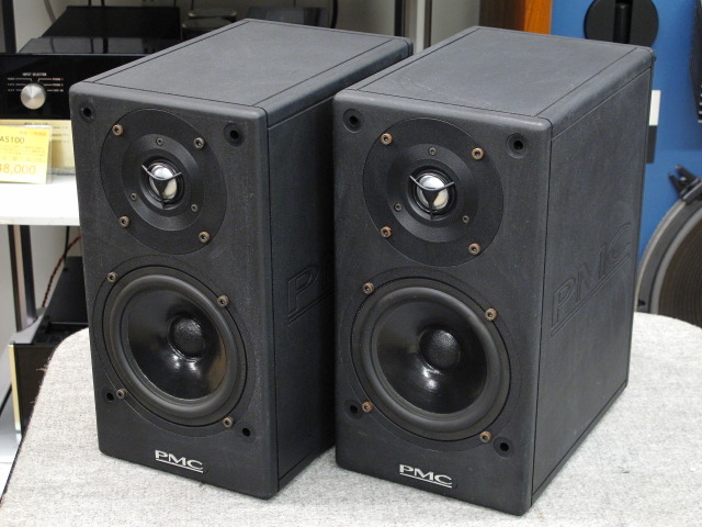
The original version of the DB1 used a Vifa M13SG and shielded version of D25 AG 05 aluminum domes.The + versions used vifa D27 TG 35 soft domes.The originals xover is 3k with 12db electrical slopes.Later versions lowered the xover point to 2k with steeper slopes.Does anyone have dimensions of this TL, and the XO frequency and slopes? I would like to model it in Akabak. I believe it uses the P17Wj 6.5in woofer and the D25AG-35 tweeter. Are these the correct drivers?
This one has a silk dome tweeter:
An externally hosted image should be here but it was not working when we last tested it.
There seems to be an older version with an aluminum dome tweeter:
It seems to be the PMC posterboy for the ATL as shown in many cutaway images such as this one (I could extract dimensions from this image, but easier if someone has actually measured one or has provided specs):

Although I am tempted to just make a smaller homage from scratch using an Aurum Cantus AC130F1 and a Dayton ND25FA-4.
Last edited:
This part of quote from Bailey from Post #72: ...until the effective pipe-length is less than one-sixth of a wavelength.
Reminds me of a guy ("villastrangiato" was his user name, I believe) from several years ago that claimed that a line would resonate at its 1/6 wavelength frequency, could not be tapered and had to possess only a single impedance peak in order to be a "true" TL, and is what Bailey was talking about.
Hmmmm?
Paul
The brochure of the PMC TB1 is here: https://pmc-speakers.com/sites/default/files/attachments/TB1-Brochure.pdf
I assume there are only two divider boards in the cabinet (as shown in the TB2 drawing), giving three divisions of constant cross sectional area and a total line length of about 1.2 m.
BTW, the 1st article of Bailey is from 1965: http://diyaudioprojects.com/Technical/Papers/Non-resonant-Loudspeaker-Enclosure-Design.pdf
The brochure says it uses 6dB/oct crossovers. With a step baffle for delay these may have been transient perfect. ?
The original TB1 used 6db electrical slopes.The woofer used was the Vifa M17W or the SG sheilded version.The pics in post #29 & 76 are all of the DB 1.The brochure says it uses 6dB/oct crossovers. With a step baffle for delay these may have been transient perfect. ?
Link for PDF says "Forbidden"
Don't know why. I tried Google "Arthur Bailey transmission line 1972". The Google link let me in.
http://www.google.com/url?sa=t&rct=...tTo_ECsZVW6rcBHHqJF8IQ&bvm=bv.105841590,d.cGU
- Status
- Not open for further replies.
- Home
- Loudspeakers
- Multi-Way
- PMC TL Stuffing