Second channel finished today. Both playing music now.
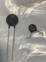
In the upgrade process I lowered the resistors in the crc filter from 0.5r to 0.083r and changed also the ntcs in the primary of the trafos.
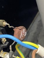
One ntc failed recently. The case broken apart but it still was working.
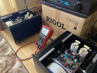
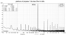
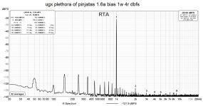
Now I have 25V under load and the bias is set at 1.6a for the moment but I plan to go higher to 2.2a(the bias for eqch mosfet is half).
A big thanks to Pa and ZM!
In the upgrade process I lowered the resistors in the crc filter from 0.5r to 0.083r and changed also the ntcs in the primary of the trafos.
One ntc failed recently. The case broken apart but it still was working.
Now I have 25V under load and the bias is set at 1.6a for the moment but I plan to go higher to 2.2a(the bias for eqch mosfet is half).
A big thanks to Pa and ZM!
Attachments

One small question.. the led in the collector of the vas bjt starts to flash on high level of input signal because the stage leaves class a and needs more bias? Or because something else?
first time hearing about that ..... when I was testing it, it didn't happened even in clipping of OS
both channels?
what type of LED you use?
both channels?
what type of LED you use?
Yes, on both channels
apt1608cgck green leds
I use toshiba mosfets in the os, they clip later compared to irfps due to the lower vgs.
apt1608cgck green leds
I use toshiba mosfets in the os, they clip later compared to irfps due to the lower vgs.
the led starts to blink at ~22.5-23Vp into 4ohm so at ~130w peak.
The rails are 25.3v and sag to 24.7v when the led starts to blink
The rails are 25.3v and sag to 24.7v when the led starts to blink
then, who cares
2V1 across your LEDs, vs. 1V93 across regular 3mm green LED - means slightly higher Iq in BD pair (dictated with 43R between emiters; so 14.6mA vs. 18.6mA)
which means slightly higher base current .... but that's irrelevant difference, in dynamic peaks where LED is approaching one or other rail you have situation of voltage/current starved LED which even parallel connected electrolytic cap can't cover ....... so - when clipping BD buffer, blinking LED is least of problems, and you can freely ignore it
I mean - I'm not expecting that you're going to use it like that all the time, while in normal power range usage, everything is more than stable
if anything - increase value of cap parallel to LED, but then you'll have slower recovery of LED voltage when going "down" from clipping moments
don't use force - use bigger hammer
so, just build bigger amp
I measured 1.91V2V1 across your LEDs, vs. 1V93
Not exactly, was curious what happens when the led was behaving like that.I mean - I'm not expecting that you're going to use it like that all the time
Seems like a nice indicator for clipping.
For now this one is more than enough and close to the max dissipation my heatsinks can take without extra cooling and also for my 80w rms(120w peak speakers). I can say a perfect match for my speakers (at least for now 🙂 )don't use force - use bigger hammer
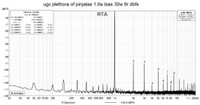
From simulation it does more than 80wrms into 4 ohm and more than 40w into 8ohm without too much thd.
More important is that I like the sound, sounds powerful like the bridged boo but a lot cleaner specially at high power levels.
When the led starts to flash the distortion is still not perceived. I have to go a little further with increasing the input level.
Now I can say that my AJ was successfully replaced and my desire for better efficiency was met, it was a nice journey until the next one..
I still have to mount a upc1237 speaker protection and then happily close the lids.
Ps. To make it shake the cage properly I had to invert the speakers wires.

The spectrum charts look great. Congratulations.
I'm curious what is the output impedance or DF. Could you measure it with 4R and 8R loads?
I'm curious what is the output impedance or DF. Could you measure it with 4R and 8R loads?
 I think I have to write a nice love letter to ZM
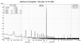
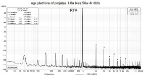
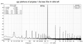
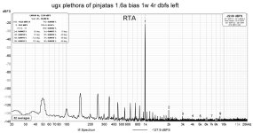
Changing the gain stage in front on the preamp gave a bit better results and an interesting thd profile, this time the same on both channels.
Attachments
good
exactly what I'm always trying to accomplish - same THD Spectra through entire ( or most of ) power range

exactly what I'm always trying to accomplish - same THD Spectra through entire ( or most of ) power range
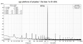
out of curiosity I measured also into 8 ohms.
next step will be to add active rectification and voltage regulators to the rails. this to have something further to learn and experiment, the amps are dead quiet as they are now.
next step will be to add active rectification and voltage regulators to the rails. this to have something further to learn and experiment, the amps are dead quiet as they are now.
Attachments
- Home
- Amplifiers
- Pass Labs
- Plethora of Pinjatas / SET P amp(s)