Hi !
Argh......why don't you look in this Thread ?
I did a Tube stage already, a ß-follower. Look here
Thats the problem with these huge threads here...
Well, I'm planning a new one, because the ECC88 can sound better with more current flowing through it.
Actually im working on a µ-follower with ECC40 and E280F.
Of course, it is DC coupled to the DAC
Manta
repaired scph-1001
So I found out that the repaired scph-1001 that I bought had it's laser replaced only, and that everything else is original to the machine. Should a replaced laser change the sound quality? (Sorry for my ignorance.)
So I found out that the repaired scph-1001 that I bought had it's laser replaced only, and that everything else is original to the machine. Should a replaced laser change the sound quality? (Sorry for my ignorance.)
Replacing laser will change nothing. Very little on the digital end will make a difference.
The SCPH-1001 is a decade old. Most original lasers are worn out. The SCPH-1001 CDM is especially susceptible to mechanical wear. It's almost all plastic. The sled on subsequent models is made of metal.
Edit: I agree. A separate tube mod thread is in place.
The SCPH-1001 is a decade old. Most original lasers are worn out. The SCPH-1001 CDM is especially susceptible to mechanical wear. It's almost all plastic. The sled on subsequent models is made of metal.
Edit: I agree. A separate tube mod thread is in place.
phn said:Replacing laser will change nothing. Very little on the digital end will make a difference.
The SCPH-1001 is a decade old. Most original lasers are worn out. The SCPH-1001 CDM is especially susceptible to mechanical wear. It's almost all plastic. The sled on subsequent models is made of metal.
Edit: I agree. A separate tube mod thread is in place.
Hi all!
Has someone made tube output stage and share experiences?
I made contact with seller for tube output stage and he wants 280 EUR for that.
Trying to make contact with Michael Methe, but email is returning as Undelivered Mail.
His page: http://www.methe-family.de/cd.htm
I also agree that SCHP-1002 sounds great. I bypass output stage and add 4.7uF Vishay capacitor and 47k Vishay-dale resistor.
It is first player, which i can listen also complex music, like classical (usually became mudded and unpleasant).
With good tube output stage it could be even better.
I didnt make yet separate PSU, i will do.
Thank you for sharing experiences.
regards, Bostjan
As said earlier, making a tube output should be simple. But first you need to decide what you want and you have to take into account the limited gain needed, ideally 6db or less.
phn said:As said earlier, making a tube output should be simple. But first you need to decide what you want and you have to take into account the limited gain needed, ideally 6db or less.
Someones has done it with ECL86 or ECC88. Both is OK.
Personally i dont need much gain.
Any sugestions?
phn said:There's a tube output in post 1182 using the ECC88. I believe I linked to a simple design using the same tube. Should be some posts back.
I have nothing on the ECL86.
Hi,
thanks. I will try ECC88 output stage.
regards, Bostjan
model #???
SCPH-1001-94000
is this the prefered model to use for a cdp? i'm confused because of the last 5 numbers.
thanks, j
SCPH-1001-94000
is this the prefered model to use for a cdp? i'm confused because of the last 5 numbers.
thanks, j
I don't know what the 94000 is. But, yes, it looks to be an SCPH-1001. It should be easily identified since it's the only PlayStation to come with RCA jacks.
Hey guy's just modding another PS1 and was about to connect the ground wire of my bypass wires to a place that is supposed to be connected to the analog ground pin on the DAC... but it shows 15K to the general ground on the board.
Should I use this one or just pick up one of the general ground planes?
Thanks chaps
Should I use this one or just pick up one of the general ground planes?
Thanks chaps
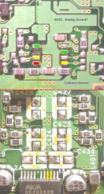
This is the area I'm talking about... AVSS analog ground?...
If you fold the picture along the red line you have a mock-up of the board.....
It is the analog ground for both Opamp inputs as you can see (opamp removed) and is connected to the common board ground by that 15K SMD.
I'm assuming that the solder blob on the underside of the board is covering a throughhole to the AVSS pin of the DAC.
Attachments
Hello all,
What wood be better for little amplifier on output stage : a voltage-amplifier or a current-amplifier or a combination of the two ?
Thanks for reply.
What wood be better for little amplifier on output stage : a voltage-amplifier or a current-amplifier or a combination of the two ?
Thanks for reply.
Ah well, just reboxed my PS1 and plugged her in...
Right channel good! 😀
Left channel dead🙁
When I turn the pot I just get static and 5V DC out of one channel (2.6 on the other) do you think the DAC has gone or could it be the transport?
The schematic is extremely simple at the moment with a 50K pot wired in straight after the DAC pins and then blocking caps after that so you can hear the DC when you turn the pot on the bad channel. This feeds a T-amp so the caps need to between the pot and amp (Bias voltage on it's imput). I could put another set before the pot but I didn't think it would really matter.
Anyone got a spare PS1?🙁
What are you doing?
It's so simple. pin 15 and 16. AKM /AK 4310VM outputs. After that use some PIO capacitors, 10 microfarad,and after that a resistance to ground , some 100 kohms. And better:
after that use a simple ampli tube or a fet ampli...with pio capacitors !
For phase : the direct output of the DAC is ( I think is in absolute phase ). It's more better with a little enforcement for better dynamics, so a small ampli after the ouput is lovely... ( I think a voltage stage ampli, not a current ampli )
Someone?
I never hear a cd player so nice like THE PSX ! But mounting the driver unit on a construction in plywood ( spruce or pine ) is important : not a metal plate !
sigurd said:What are you doing?
It's so simple. pin 15 and 16. AKM /AK 4310VM outputs. After that use some PIO capacitors, 10 microfarad,and after that a resistance to ground , some 100 kohms. And better:
after that use a simple ampli tube or a fet ampli...with pio capacitors !
For phase : the direct output of the DAC is ( I think is in absolute phase ). It's more better with a little enforcement for better dynamics, so a small ampli after the ouput is lovely... ( I think a voltage stage ampli, not a current ampli )
Someone?
This is the 3rd PS1 I've modified and I prefer it with no buffer or anything in the signal path so I try and keep it minimalistic.
If you add a capacitor you change the sound so the fewer bits the better.
I have it running like this in it's original case but after re-casing it developed this problem. Must have disturbed/damaged something.
I was just wondering if it could be the laser cable that has a bad connection......
loss of a channel . I recall I had this problem earlier in the thread with the configuration of the output resistors. The RCA plus have a shorting function so that if you connect the PS UHF Mux into it it sums the two channels and provides a mono down mixed version via one of the out RCA's. This doesn't explain why a rebox looses a channel but it does explain why the poutput mod does. Check out the earlier posts in this thread. Mick_F's mod avoids this problem by his choice of earth point for the resistor
Thanks for the reply sir but I have completely bypassed everything and jumped off the pins straight to the pot and used a common ground as shown in a few posts above.
Even if I put an extra cap and resistor combo in there it will still have the same problem.
I was wondering if the signal may not even be getting to the DAC? Maybe it's the cable connections for the transport? I'll open her up at the weekend and have a look.
Even if I put an extra cap and resistor combo in there it will still have the same problem.
I was wondering if the signal may not even be getting to the DAC? Maybe it's the cable connections for the transport? I'll open her up at the weekend and have a look.
- Home
- Source & Line
- Digital Source
- Playstation as CD-player