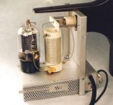
Hello Lampie 519,
I think now no C3 more !
First,as you Says: it stop the DC current to anode.
Second:even just behind L1, in front of the T junction ,L1 and C3 become an other LC circuit.
So L1 must be alone.
I think now no C3 more !
First,as you Says: it stop the DC current to anode.
Second:even just behind L1, in front of the T junction ,L1 and C3 become an other LC circuit.
So L1 must be alone.
Hello,
New schematic:
I keep C1 but at the good place.
New schematic:
I keep C1 but at the good place.
An externally hosted image should be here but it was not working when we last tested it.
Last edited:
You can save your “pio” for a better application. It is no use here, ceramics are best here. But this design will work.
Best regards, Frank
Best regards, Frank
There is no point of putting ceramic cap instead of paper/oil in a parallel to the film one before DC feed inductor, particularly at this power level. Perhaps motor run PP cap?
Theorically my 0,1 uf PIO capacitor does the job better than a 10nf ceramic capacitor.So why C. Willis use both?
I don’t say it is no good but not of any help here. This is a power oscillator and will just work fine without any pio. I would be surprised if you can hear the difference here. Decoupling in an audio amp is a different story. Decoupling the heaters is important here. C6 helps starting the oscillator, that’s all. C5 prevents any HF getting to your audio amp, this could be a silver mica or ceramic c. It is not the best for audio but best for decoupling HF. Audio guys do usually think that ceramics are no good, but this is no audioamp. Radioamateurs can tell you all about decoupling HF circuits. And this is what a plasma tweeter is. The stages before the oscillator are audio related and can be treated with high quality audiophile components as much as you like.
Best regards, Frank
Best regards, Frank
One more thing: Don’t forget the parasitic supressor in the anode circuit. Please check the schematic i have provided earlier. Use a 100 Ohm resistor and wind some copperwire arround it. Use a big resistor it can get hot!
Thanks a lot Lampie 519,but i don't see your schematic that you have provided.
But I have mounted early the PIO capacitor before my post with schematic.
Impédance of PIO capacitor is less than the ceramic one.And a great news :you writed that it help the system to start it self.So i keep it !
Before i read your last post I have throwed my 12 nf ceramic capacitor.
For parasitic suppressor what kind of resistor should i use:métal film ,or carbon film ?Please.
Industance will be not the same.
I have any 5w carbon film pièces.
Regards
Carbon 5 watt is fine. 10 windings copper arround it. For the schematic go to post 258. Who told you that pio has less esr? That is new to me. Same value? I guess not.
Hello Lampie 519,
No 5w resistor,but 2w only.
Size of one resistor: around 15 mm long and 5 to 6 mm diameter.
10 turns seems to me difficult.
Thanks for schematic .I printed it.
For capacitor ,I think that i understood. I will re-weld a 12 nf capacitor.
Pictures will come another time.
But for the moment,coils and most parts are builded.
Regards
have a look,please:
Oops I let the smoke out!! SB-220 parasitic suppressors, carbon resistors split open | QRZ Forums.
should a coil on the side of the resistor be better than around ?
Oops I let the smoke out!! SB-220 parasitic suppressors, carbon resistors split open | QRZ Forums.
should a coil on the side of the resistor be better than around ?
Last edited:
It has been working for 50+ years without issues, so i guess if you don't do anything strange it will work just fine!
Done after work:
6 turns 1,5mm diameter around 100 Ohms 2w carbon film resistor .Should it work ?
6 turns 1,5mm diameter around 100 Ohms 2w carbon film resistor .Should it work ?
An externally hosted image should be here but it was not working when we last tested it.
Looks good! But now you need to fix them to the tube. You can not use solder here. Crimping is best. As it gets hot it would melt the solder or break the joint.
First biild it. Then you will see and learn !
Hello Lampie 519.
An externally hosted image should be here but it was not working when we last tested it.
I tried to understand how does parasitic suppressor work,but in vain
Tube CAG is 0,2Pf ,at 35Mhz it comes 22,8k.
Impédance of parasitic suppressor is few Ohm,(less than 50).If i throw it,what's happening ?
Highs frequencies ?Low fréquencies ?
Regards
- Home
- Loudspeakers
- Planars & Exotics
- Plasmatweeter
