This noise reduction method is better (easy). It integrates
most of wenzel's ultra shunt into one little package.
--
So , just a LM317 (emp) sot232 IC plus another smd BJT (and a few caps/
resistors) gives at least twice the performance as the standard IC
shunt.
OS
+ Small PCB with 78xx pinout sell $$$$$$$ 😀
I have opamp for 5v LTC1050, max492 (scrap from some module)
+ Small PCB with 78xx pinout sell $$$$$$$ 😀
I have opamp for 5v LTC1050, max492 (scrap from some module)
Wow ! the LTC1050 is 125db pssr , 1.6uV noise , and runs >4.7V single
supply.
The op-amp was the major noise contributor to wenzel's ultra shunt.
>5uV/hz might be possible with the LTC.
OS
used for clocks/vco/osc to get ultra clean references, low phase noise. Higher jitter closes the eye in synchronous clocking systems increasing transmission error rate. Jitter in digital is akin to noise, non-linearity(distortion) in analog.I guess where you use this tech depends on how sensitive the digital
IC is to the noise ??
Also a jittery clock will degrade setup/hold times as well.
Lots of good LN reg solutions, Micrel/Lintech have nice parts for sure.
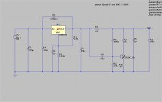
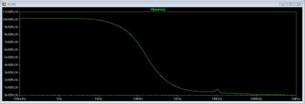
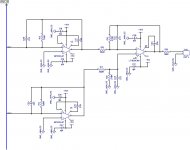
Tinkering with the wenzel shunt. It works well !!
I saw the "squeezebox" DAC supply , simulated it.
Pretty good at 50nV/hz ...but I can get <10nV/hz with the wenzel.
(below 1) is the circuit , and (below 2) is the simulated noise.
5.04V out , 5mA shunted , 50ma max current for the posted circuit.
Wenzels shunt cut the 317's 300nV noise down by a factor of 30+.
Edit - A "squeezbox" LM723 regulator plus this shunt would be phenomenal.
OS
Attachments
Last edited:
I always like LM(uA)723, i guess that is why it is still in production.
What Logitech squeezbox are you talking about? link pls
What Logitech squeezbox are you talking about? link pls
Tinkering with the wenzel shunt. It works well !!
I saw the "squeezebox" DAC supply , simulated it.
Pretty good at 50nV/hz ...but I can get <10nV/hz with the wenzel.
(below 1) is the circuit , and (below 2) is the simulated noise.
5.04V out , 5mA shunted , 50ma max current for the posted circuit.
Wenzels shunt cut the 317's 300nV noise down by a factor of 30+.
Edit - A "squeezbox" LM723 regulator plus this shunt would be phenomenal.
OS
Is this regulator ready to go or are you still perfecting it?
Is this regulator ready to go or are you still perfecting it?
I still am not sure what pre-regulator to pair it with. I'll have to cross match
LT's precision regulators with TI's to model anything correctly.
My gut feeling now is that you set any adjustable reg. at 5.25-5.35V ,
shunt off .25V through a resistor to get 5V with 1/30th the noise.
At least this is what has happened with all the LT regs. I've simulated
so far.
I'm still researching and looking for other precision instrumentation regulators
that might work . I have still yet to explore the common mode SMD inductors
I see on all the "squeezbox" DIY units.
Rsavas , I referred to the groupbuy "squeezebox" I saw this morning on this
forum - caught my attention .... no real magic , can do better.
OS
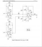
Jeff , you have not finalized the buffer ?
I was thinking , we might want to output it to headphones and
have you considered heatsinking for the buffer outputs ?
they run 80-100ma class A at 12-15V rails ... no major thermals ..
but more than a heavily biased VAS.
OS
I was thinking , we might want to output it to headphones and
have you considered heatsinking for the buffer outputs ?
they run 80-100ma class A at 12-15V rails ... no major thermals ..
but more than a heavily biased VAS.
OS
Jeff , you have not finalized the buffer ?
I was thinking , we might want to output it to headphones and
have you considered heatsinking for the buffer outputs ?
they run 80-100ma class A at 12-15V rails ... no major thermals ..
but more than a heavily biased VAS.
OS
The buffer outputs can be mounted under the board. There's through holes in the board. I've got line out and headphone out relays on the output board too. Does the DAC output go directly into the linestage or is there something that goes between?
Last edited:
The buffer outputs can be mounted under the board. There's through holes in the board. I've got line out and headphone out relays on the output board too. Does the DAC output go directly into the linestage or is there something that goes between?
The DAC is just one of the inputs (sources) that will be switched.
You know , like (CD , aux , DAC , TV ... etc).
Then whatever source is selected goes to the attenuation.
Attenuator output goes to the final buffer.
OS
OS,
Reading the ESS dac page when I was looking they had one unit that had an output of 2V that could run directly into a power amp. Now are you proposing to have a dac run into the line-stage to bring up the level, is that how this will work? Since there are such loose standards for device output I can see the complications to multiple inputs. I suppose there is no way to normalize all these different inputs to the same output voltage.
Reading the ESS dac page when I was looking they had one unit that had an output of 2V that could run directly into a power amp. Now are you proposing to have a dac run into the line-stage to bring up the level, is that how this will work? Since there are such loose standards for device output I can see the complications to multiple inputs. I suppose there is no way to normalize all these different inputs to the same output voltage.
OS,
Reading the ESS dac page when I was looking they had one unit that had an output of 2V that could run directly into a power amp. Now are you proposing to have a dac run into the line-stage to bring up the level, is that how this will work? Since there are such loose standards for device output I can see the complications to multiple inputs. I suppose there is no way to normalize all these different inputs to the same output voltage.
100K trimmer at each line input ... a preset on the attenuator for each input.
Many ways to normalize inputs.
If your flac/mp3 is a lower DBu , at least the buffer would give you the choice
of gain more than 1:1. The DAC would only output what the digital PCM
tells it to.
The op-amps at the DAC output could also be gain adjusted.
The buffer is also way superior in transmitting a low Z signal over 6-12'
of audio cable to the amp.
The buffer also assures that +3 - +6db will have plenty of headroom at output. (and drive headphones).
OS
Thanks OS. since I am looking at putting a dac directly inside the enclosure with the amp and speakers how do you handle having a single unit inside one of the enclosures and get signal to the second amp. I see then you would want the buffer at least to send the signal to the second speaker that can be as far apart as the user puts them. Would you just use a typical RCA interconnect between enclosures?
I meant can we take the output directly from the DAC IC output pins or does it need an op amp in between?
I Use cat6 cables and connectors for signal. With four pairs, you can manage what you want the way you want inside you enclosures.Thanks OS. since I am looking at putting a dac directly inside the enclosure with the amp and speakers how do you handle having a single unit inside one of the enclosures and get signal to the second amp. I see then you would want the buffer at least to send the signal to the second speaker that can be as far apart as the user puts them. Would you just use a typical RCA interconnect between enclosures?
In my system, basses, medium/trebles, power on, volume control from my active filter for each enclosure. I use a sub, with only 3 signals: sub basses, power on, volume control.
In your case, you can put an in and out RJ45 on each enclosure and a switch to chose left/right ?
Jeff , you have not finalized the buffer ?
I was thinking , we might want to output it to headphones and
have you considered heatsinking for the buffer outputs ?
they run 80-100ma class A at 12-15V rails ... no major thermals ..
but more than a heavily biased VAS.
OS
I just took another look at my linestage layout. The shunt pass transistors are chassis mount, but not the output buffers. I'll see if I can shuffle some parts around and do this. I'm still playing with the idea of an optional backplane to eliminate loose signal and power wire so nothing will be finalized until I can get all the boards figured out.
I meant can we take the output directly from the DAC IC output pins or does it need an op amp in between?
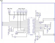
Some DAC's need external op-amps for the I/V and filter (below- pcm1794)
For just a DAC in a box , fine ... use the filter as the main buffer.
Newer auto/mobile ones - http://www.ti.com/lit/ds/symlink/pcm5121.pdf
...have the DAC + I/V - filter all in one. No buffer really needed if for a standalone app.
However , the externally buffered/converted DAC's offer greater performance
and flexibility (roll yer' IC's 😀 ).
Multiple input preamps with attenuators should have a dedicated main buffer
as some inputs won't be pre-buffered , like the DAC is.
OS
Attachments
Some DAC's need external op-amps for the I/V and filter ...
Pete,
I invite you to take a look at using the TI OPA1632 Dual Differential part. They work very, very well in this application. I remember seeing an excellent audio applications note for this part. However I just went looking for it and cannot seem to find it! Argh ...
Here's what I've gotten put together for the DAC so far. I'm still trying to figure out something for USB input but it's looking like a ready made daughterboard is the way to go there.
I also need to add an optical connector yet too.
I also need to add an optical connector yet too.
Attachments

- Home
- Source & Line
- Analog Line Level
- Pitchfork pre-amplifier