Ready to check
OK, I'm ready to check pins 8,1,12,22 at the power amps now.
On the PSU I see resistors (silk sleeved) on 22-24 and 25-27 - but I fail to find them on the schematic?
I'll unsolder and check values...
OK, I'm ready to check pins 8,1,12,22 at the power amps now.
HTML:
Power amp assy, Left CH
+	-	V(actual)	V(Specs)	remarks
1	chass	-3,00		-60,00		slow up&down
8	chass	+80,00		+60,00		quick power-off to prevent damage
12	chass	+62,00		+62,00
22	chass	-62,00		-62,00

Power amp assy, Right CH
+	-	V(actual)	V(Specs)	remarks
1	chass	-2,80		-60,00		slow up&down
8	chass	+80,00		+60,00		quick power-off to prevent damage
12	chass	+62,00		+62,00
22	chass	-62,00		-62,00
----------------------------------------------------------------------------------
Power supply
+	-	V(actual)	V(Specs)	remarks
22	chass	+63,80		+60,00		pin 8
27	chass	-2,30		-60,00		pin 1
On the PSU I see resistors (silk sleeved) on 22-24 and 25-27 - but I fail to find them on the schematic?
I'll unsolder and check values...
Last edited:
OK.
Resistor on pins 22-22 is labeled 1.2K, reads 1.10K
Resistor on pins 25-27 is labeled 1.2K, reads 1.16K
Should be good enough.
Resistor on pins 22-22 is labeled 1.2K, reads 1.10K
Resistor on pins 25-27 is labeled 1.2K, reads 1.16K
Should be good enough.
That's fine, they are visible on overall schematic...
Something is still wrong with -60v psu channel
Can you pls check that Q4 is also soldered correctly (b-c-e are in the right places)...
It would be also useful to disconnect the wires 22 and 27 from PSU - just to be on a safe side
We need to get -60v at 27 first, before connecting anything there
Something is still wrong with -60v psu channel
Can you pls check that Q4 is also soldered correctly (b-c-e are in the right places)...
It would be also useful to disconnect the wires 22 and 27 from PSU - just to be on a safe side
We need to get -60v at 27 first, before connecting anything there
Attachments
Last edited:
That's fine, they are visible on overall schematic...
Ahh, good - I should have that in mind, in stead of just having the unit-schematic
Thinking about 80v
Yes - I guess this is the next to solve.
I just did a test with a replacement for Q5, but it made no difference to PSU pin 27 - still -2.3V
Looking to replace Q6, but I rather wait, since it's like a long shot.
Ping 27 connects to pins 2 on the protection unit - maybe this is a place to check?
it has to give -60v even without the load - that is why it will be useful to disconnect everything from pin 27 and make it giving this -60v
Then we can go ahead
-2.3v means something is seriously wrong with the transistors (Q3, Q4)
Let's check again
Then we can go ahead
-2.3v means something is seriously wrong with the transistors (Q3, Q4)
Let's check again
Last edited:
More readings
OK, now I took readings on the PSU and on the protection assy:
Q3 which shows bad values, was the one that blew, and was replaced today...
Perhaps some of these readings can give a clue. 😕
OK, now I took readings on the PSU and on the protection assy:
HTML:
----------------------------------------------------------------------------------
2nd reading on Power supply
----------------------------------------------------------------------------------
Power supply		'->': My symbol for "slow, steady increase"
+	-	V(actual)	V(Specs)	remarks
Q3c-Q4b		- 2,30				same as pin 27
Q1b	chass	+64,6+		+60,6		->; OK?
Q1e	chass	+63,8+		+60,0		->; OK?
Q3e	chass	0,0000		+13,0		bad
Q3b	chass	- 0.5		+13,6		bad
Q5e	chass	13,00		+13,0		good
Q5b	chass	13,60		+13,6		good
Q6e	chass	13,60		+13,6		good
Q2b		+14,80		+14,8		good
R12		+14,80		+14,8		good
R13		+14,80		+14,8		good
D6-R9		+26,80		+24,00		ok
---------------------------------------------------------------------------------
+	-	V(actual)	V(Specs)	remarks
7	chass	+ 1,99		+62,00		bad
8	chass	-62,50		-62,00		good
16	chass	+12,80		+13,00		good
19	chass	+82,00		+76,00		not so good
20	chass	35,->		+33,00		->
22	chass	+63,5'		+60,00		ok
23	chass	+23,50		+23,00		good
25	chass	- 0,70		-23,00		bad
27	chass	- 2,30		-60,00		bad, pin 1 on power amp
28	chass	 0,0000		-13,00		bad
Q3 which shows bad values, was the one that blew, and was replaced today...
HTML:
----------------------------------------------------------------------------------
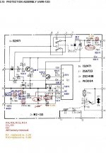
Protection assy
+ - V(actual) V(Specs) remarks
2 chass -2,30 -60,00 pin 1 power amps, pin 27 PSU
9 chass +12,80 +13,00 various connections
10 chass +81,60 +76,00Perhaps some of these readings can give a clue. 😕
Q4 has same pin layout, and checks correct by comparing to previous mounted 2SB682.That's fine, they are visible on overall schematic...
Something is still wrong with -60v psu channel
Can you pls check that Q4 is also soldered correctly (b-c-e are in the right places)...
It would be also useful to disconnect the wires 22 and 27 from PSU - just to be on a safe side
We need to get -60v at 27 first, before connecting anything there
OK, 22 and 27 are cut now
(didn't see your edit until now (01.00 CPH)
Picking up on the project again.
Since I have been unable to track down the error on the power amps, I backtracked to the power supply where I found a few issues:
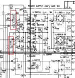
pin 20,22 and 23 are way off:
pin 20 reads +11,7V should be +33V
pin 22 reads +18.6V should be +60V
pin 23 reads + 6.5V should be +23V
Power supply - schematic w. readings: Thumb 1.
Before this Q3, D9 and R6 were fried, but even after replacement, these bad values remain.
During diagnostic tests D10 and D11 have been replaced, but without any improvement/change, and until I can get hold on a D8 (Zener 14V) it is an unknown (doesn't seem to be available in DK, but I'll have a couple added to the back order I have with mouser: New 22000µFs 🙂 ).
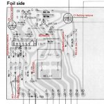
I did also look into the protection assembly, which has no less than 7 modifications compared to the Service Manual:
Protection assy - foil view w. modifications: Thumb 2.
The readings I get seem correct, the modifications taken into account, but I may be wrong?
Protection assy - schematic w.readings: Thumb 3.
I've checked and re-checked the power supply, and to the best of my knowledge all components are mounted correcty.
By now I'm dry for ideas, so I hope for a hint that will take me to the next step.
/Ole
Since I have been unable to track down the error on the power amps, I backtracked to the power supply where I found a few issues:
pin 20,22 and 23 are way off:
pin 20 reads +11,7V should be +33V
pin 22 reads +18.6V should be +60V
pin 23 reads + 6.5V should be +23V
Power supply - schematic w. readings: Thumb 1.
Before this Q3, D9 and R6 were fried, but even after replacement, these bad values remain.
During diagnostic tests D10 and D11 have been replaced, but without any improvement/change, and until I can get hold on a D8 (Zener 14V) it is an unknown (doesn't seem to be available in DK, but I'll have a couple added to the back order I have with mouser: New 22000µFs 🙂 ).
I did also look into the protection assembly, which has no less than 7 modifications compared to the Service Manual:
Protection assy - foil view w. modifications: Thumb 2.
The readings I get seem correct, the modifications taken into account, but I may be wrong?
Protection assy - schematic w.readings: Thumb 3.
I've checked and re-checked the power supply, and to the best of my knowledge all components are mounted correcty.
By now I'm dry for ideas,
so I hope for a hint that will take me to the next step./Ole
Attachments
Hi Ole,
Looks strange. Remember, we were fighting for -60V rail (pin 27 of power supply), which did not work?
From what I see at your drawing, it is ok now (showing -64.25, which is acceptable).
Now +60V rail (pin 22) does not work. Did you change Q2 or something in the upper side of the schematic?
Cheers,
Valery
Correct, Valey, D9 has been replaced, since the latest readings I have posted.
I guess I'll have to wait until the MZ-140 14V zener arrives before there can be any new meaning ful tests 😕
Yes, D9, R6 were fried, and Q3 was replaced once more, just in case (was new), which moved the faulty reading from pin 27 to pin 22 - sorry, I seem to loose track along the way between posts😀
Ah, ok - this is what I thought 🙂
I hope after replacements we have both 60V rails working - then we can move forward with the power amps...
I hope after replacements we have both 60V rails working - then we can move forward with the power amps...
Ah, ok - this is what I thought 🙂
I hope after replacements we have both 60V rails working - then we can move forward with the power amps...
Great, Valery, I'll post here once I have news 🙂
Great, Valery, I'll post here once I have news 🙂
Question:
I came to think if it is valid to build a 14V zener by 2 of lesser value that adds up to the 14 V, like fx. a 11V and a 3V, or close to like 6.8V plus 7.5V = 14.3V?
Any catches?
If yes I could start testing with a combo like that in a day, instead of waiting 5 weeks 😡
Last edited:
Yes, you can combine Zeners serially
OK, that may be worth a try, wouldn't you think?
Is it critical to match the Voltage on the decimal?
Does it matter if the values of the 2 are close to half the target value or they are like the 11+3 version?
Proportion does not matter - stabilized voltages will just summ.
If the total will hit +/-5% of original value - will be ok
If the total will hit +/-5% of original value - will be ok
Not the solution
Well I made a combo Zener of a 6.8V and a 7.5V adding up to 14.3V as a test replacement for D8 (Zener 14V), but no change in voltages for pin 10,22 and 23, which still has these readings:
pin 20 reads +11,7V should be +33V
pin 22 reads +18.6V should be +60V
pin 23 reads + 6.5V should be +23V
, both with and without C17 in place
I did check up on both the old, original and the new zeners with this setup:
Increasing the power supply past the voltage rating of the zener, the DMM will follow the increase until the rating of the zener.
Using the above setup I get voltage readings on the DMM, that corresponds to the voltage rating on the zener diodes, for all 3 D8, D10 and D11 (14/22/22 volts) for both old and new diodes within 0.5V. It even hits exactly th 14.3 volts for the test combo.
This means the error must be somewhere else, but where could it be?
I took some more readings I haven't done before:
pins 5 & 6: AC 45.00V
pins 10 & 11: AC 61.25V
Any hints from this?
I feel I'm running out of options, since I see no further path to pursue.😡
Well I made a combo Zener of a 6.8V and a 7.5V adding up to 14.3V as a test replacement for D8 (Zener 14V), but no change in voltages for pin 10,22 and 23, which still has these readings:
pin 20 reads +11,7V should be +33V
pin 22 reads +18.6V should be +60V
pin 23 reads + 6.5V should be +23V
, both with and without C17 in place
I did check up on both the old, original and the new zeners with this setup:
HTML:
      +--------------- 30v DC power supply ----------------+
      |                                                    |
      |                                                    |
      |                                  Zener xV          |
neg|--+--------\/\/\/\/\/\/\/--------o------>|------o------+--|pos
                    4.7K             |              |
                                     |              |
                                     |              |
                                     |              |
                                  neg+---  DMM  ----+pos
Increasing the power supply past the voltage rating of the zener, the DMM will follow the increase until the rating of the zener.
Using the above setup I get voltage readings on the DMM, that corresponds to the voltage rating on the zener diodes, for all 3 D8, D10 and D11 (14/22/22 volts) for both old and new diodes within 0.5V. It even hits exactly th 14.3 volts for the test combo.
This means the error must be somewhere else, but where could it be?
I took some more readings I haven't done before:
pins 5 & 6: AC 45.00V
pins 10 & 11: AC 61.25V
Any hints from this?
I feel I'm running out of options, since I see no further path to pursue.😡
Good news
Ahhh, finally some positive to report 😀
To cut it short the error regarding the voltage on pins 20, 22 & 23 is now solved. The culprit was a broken trans, namely Q2, which makes a lot of sense when you look at the schematic.
All voltages are now within +- 0.5-1.0 V.
I received the latest parts from mouser yesterday, and now the power supply has been allmost completely rebuildt. The only parts that hasn't been replaced are the D5 bridge and the ceramic capacitors.
Later today (or possibly tomorrow) I will reassemble the unit - the power amps have been unmounted, and I also have some new main caps to install.
🙂
Ah, great!
If the power supply will give us the right values, we can move ahead to the power amps.
Just to be on a safe side, is you put the amps back, don't connect the big output transistors - it will make sense to switch the amps on without them first. Much safer! 😉
- Status
- Not open for further replies.
- Home
- Amplifiers
- Solid State
- Pioneer SX-1080, after re-cap problem w. center voltage & idle current