Ready to continue
OK, I have reassembled it now:
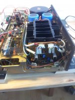
mounted amps
mounted amp cooler
connected molex'es to amps
and left the big output caps unconnected
(just to be 100% sure - you wrote 'big output transistors' but it is caps? Sorry if this is too nitty-gritty, but I would hate to misinterpret something).
Another thing I worry about:
After the initial power-up, I was trimming the center voltage with the multi-turn pot VR2 on the right ch amp I turned and turned until something became overloaded, and all the problems started.
So before I power on I would like to be safe in that respect and therefore I have pre-adjusted it to approx. 40 KOhm.
Can I power-on without risking blowing something up?
Ah, great!
If the power supply will give us the right values, we can move ahead to the power amps.
Just to be on a safe side, is you put the amps back, don't connect the big output transistors - it will make sense to switch the amps on without them first. Much safer! 😉
OK, I have reassembled it now:
mounted amps
mounted amp cooler
connected molex'es to amps
and left the big output caps unconnected
(just to be 100% sure - you wrote 'big output transistors' but it is caps? Sorry if this is too nitty-gritty, but I would hate to misinterpret something).
Another thing I worry about:
After the initial power-up, I was trimming the center voltage with the multi-turn pot VR2 on the right ch amp I turned and turned until something became overloaded, and all the problems started.
So before I power on I would like to be safe in that respect and therefore I have pre-adjusted it to approx. 40 KOhm.
Can I power-on without risking blowing something up?
Attachments
Last edited:
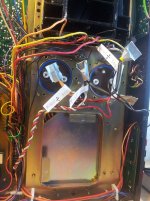
Ole, I mean those two white 4-pin plugs at the top of the picture.
Just leave them unplugged in both channels.
Having that, it is rather safe to power it on.
OK, disconnect the 2*2 4-pin connectors, and connect the wires to the terminals af the 2 big 22.000µF caps?
And then you wrote what you meant, not what I thought 😉
But, if I can ask - what flows through the 2*2 4-pin connectors - all of the output power, that in turn needs the big heat sink to dissipate the heat?
And - you don't think I should worry about the VR2 setting?
Last edited:
OK, disconnect the 2*2 4-pin connectors, and connect the wires to the terminals af the 2 big 22.000µF caps?
And then you wrote what you meant, not what I thought 😉
But, if I can ask - what flows through the 2*2 4-pin connectors - all of the output power, that in turn needs the big heat sink to dissipate the heat?
And - you don't think I should worry about the VR2 setting?
Well, just couldn't wait so I took some readings, and they all look good:
HTML:
--------------------------------------------------------
Power supply, testing without DBT
--------------------------------------------------------
+	V(actual)	V(Specs)	remarks
---
7	+62.9		+62
8	-62.9		-62
16	+12.9		+13.0
18	+13.0		(7.5)
19	+83.0		+76		was +86
20	+34.9		+33,00
22	+61.9		+60,00
23	+23.4		+23,00
25	-23.1		-23
27	-62.4		-60
28	-13.5		-13
--------------------------------------------------------
Power amp, testing without DBT
--------------------------------------------------------
Left channel:
Adjusting center voltage.
Positive lead to pin 10, negative lead to chassis
Initial reading at 225 mV
Right channel:
Adjusting center voltage.
Positive lead to pin 10, negative lead to chassis
Initial reading at 38 mV
I just took these readings to see how it was doing, and it looks pretty good for an unadjusted unit considering 0V is the aim.
Checking idle current was in vain - 0.0000V on both channels - I guess the big output transistors need to be connected to do this?
I'll await your comments before I connect the output transistors, and continue the work.
Cheers
Ole
OK, looks good )
You can assemble everything except the 2*2 4-pin connectors - let's leave them unplugged for a while. Amplifiers must behave normally even without them (without load).
38mV at the right channel is fine, though you can try to turn VR2 carefully, to see if this offset changes and try to make it as close to "0" as possible (leads are at pin10 and chassis). Turn the pot slowly and carefully and see what happens with the offset.
225mV at the left channel is definitely too much. Same procedure - leads at pin 10 and the chassis, and constantly see what happens with the voltage - try to make it "0".
The last thing - please put the leads at pins 15 (positive) and 20 (negative) and see the voltage there. Left channel, then right channel. This is an important one, we need to check it before we decide to connect the 2*2 4-pin connectors.
Cheers,
Valery
Left channel:
Adjusting center voltage.
Initial reading at 225 mV
Adjusted to -0.3mV (-0.0003V) - fluctuates to +7mV
Looks good.
Right channel:
Adjusting center voltage.
Initial reading at 37 mV
Unable to adjust r-ch. - reading does not react to turns on VR2
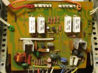
Visual inspection shows that R22 160 Ohm is damaged.
R22 was fried previously (left burn mark on PCB)
Seems like an error on right ch amp?
I'll check if I have another 160 Ohm resistor, but why did this fail again...?
Adjusting center voltage.
Initial reading at 225 mV
Adjusted to -0.3mV (-0.0003V) - fluctuates to +7mV
Looks good.
Right channel:
Adjusting center voltage.
Initial reading at 37 mV
Unable to adjust r-ch. - reading does not react to turns on VR2
Visual inspection shows that R22 160 Ohm is damaged.
R22 was fried previously (left burn mark on PCB)
Seems like an error on right ch amp?
I'll check if I have another 160 Ohm resistor, but why did this fail again...?
Last edited:
Unknown error on right channel power amp
Ok, I got my hands on a batch of all of the carbon type resistors for the power amps.
----------------------------------------
The following is right channel readings:
----------------------------------------
Replaced R22 with 165 Ohms (within +-5%: 152-168 Ohms)
Checking center voltage: 144mV (was 37mV)
Turning VR2 one half turn in both directions has no effect on reading, steady on 144mV.
Pin readings:
Saw just now that R11 (100 Ohms) is burnt - will replace.
Testing again:
Intersection C4,C5,R6:
Startet in the minus thirties, then R22 began smoking, Power-off.
R11 has discoloration, and looks ready to burn next.
Where to go from here?
Perhaps a transistor problem - if so I hope it isn't the 5 legged Q1
Ok, I got my hands on a batch of all of the carbon type resistors for the power amps.
----------------------------------------
The following is right channel readings:
----------------------------------------
Replaced R22 with 165 Ohms (within +-5%: 152-168 Ohms)
Checking center voltage: 144mV (was 37mV)
Turning VR2 one half turn in both directions has no effect on reading, steady on 144mV.
Pin readings:
HTML:
1	-62	(-60)
4	+23.5	(+23)
5	-23.2	(-23)
8	+62	(+60)
12	+63.1	(+62)
22	-62.7	(-62)

intersection C4,C5,R6:	0.16	(0.6)
intersection Q1,R3,R33:	159mV	(0.0)

Q4c	+61.3	+3	ERROR here
Saw just now that R11 (100 Ohms) is burnt - will replace.
Testing again:
Intersection C4,C5,R6:
Startet in the minus thirties, then R22 began smoking, Power-off.
R11 has discoloration, and looks ready to burn next.
Where to go from here?
Perhaps a transistor problem - if so I hope it isn't the 5 legged Q1
Definitely a transistor problem...
And unfortunately it looks like at least Q1... maybe something else.
The point is that R22 is placed at the very low-current place (this is part of global negative feedback, coming to the inverting input of the amp - right side of Q1). The base current of Q1 is very low in normal conditions. If it fries R22, it is rather high and the only reason - it is shorted (base-collector inside Q1).
So I recommend taking this amp board out and inspect each transistor.
Special attention to Q1 and Q3, Q4, Q5.
Measure resistances with the Ohm-meter. C-E must be high both directions.
B-E or B-C is very high one direction and less high the other direction.
Main point - there must be no low resistances (shortages or near-shortages).
You can start measuring without taking transistors out, but if something will look suspicious - better to un-solder the transistor, take it out and measure again...
Definitely a transistor problem...
And unfortunately it looks like at least Q1... maybe something else.
The point is that R22 is placed at the very low-current place (this is part of global negative feedback, coming to the inverting input of the amp - right side of Q1). The base current of Q1 is very low in normal conditions. If it fries R22, it is rather high and the only reason - it is shorted (base-collector inside Q1).
So I recommend taking this amp board out and inspect each transistor.
Special attention to Q1 and Q3, Q4, Q5.
Measure resistances with the Ohm-meter. C-E must be high both directions.
B-E or B-C is very high one direction and less high the other direction.
Main point - there must be no low resistances (shortages or near-shortages).
You can start measuring without taking transistors out, but if something will look suspicious - better to un-solder the transistor, take it out and measure again...
I'll start checking the transistors.
After noting test results I'll replace all that I may have left in stock, regardless - with the exception of Q1 🙁
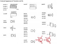
Thanks for the Quick-ref

Testing transistors:
Q1:
Impossible to test on board, so unsoldered:
Will continue with the trannys...
BTW, I saw a way to make a Q1 by combining 2 traditional 3-pin transistors (mouser 512-KSA992FBU) by markthefixer on AK, and I actually put them on my first mouser order, so maybe there is hope if Q1 is fried.
Q1:
Impossible to test on board, so unsoldered:
HTML:
c1-e:	4.0 M Ohm
b1-e:	2.2 Ohm
b1-c1:	continuously increasing past 35 M Ohm
c2-e:	6.1 Ohm
b2-e:	1.8 Ohm
b2-c2:	6.2 Ohm
Will continue with the trannys...
BTW, I saw a way to make a Q1 by combining 2 traditional 3-pin transistors (mouser 512-KSA992FBU) by markthefixer on AK, and I actually put them on my first mouser order, so maybe there is hope if Q1 is fried.
Last edited:
Yes... Q1 is gone ((
Right part of it (2) - very low values. Practically shortened.

Well, then I will look again for the possible combo fix at AK, but I suppose it will be to make a common of the emitters (hole 3) and place the collectors in holes 2, 4 and the bases in 1, 5?
Since this component supposedly is out of production this will be my only option?
Looks like there are some offers on ebay, mostly from China:
(Here)
It will be possible to put some 2 transistors (better - selected, with the same hfe).
What is coming to my mind right away - 2n5401
Not exactly the same, but good enough
Also - check the other trannies anyway...
Ahh, thanks for looking up alternatives - you just keep on letting me believe that this project will end up succesfully

 .
.I will check on the Q3-4-5 before I power-on.
But:
Will I risk doing harm if I use the combo solution for Q1?
Ahh, thanks for looking up alternatives - you just keep on letting me believe that this project will end up succesfully
I will check on the Q3-4-5 before I power-on.
But:
Will I risk doing harm if I use the combo solution for Q1?
We will make it successful - no worries 🙂
Combo will be fine - just carefully make sure the B-C-E of each individual transistor are in the right places
We will make it successful - no worries 🙂
🙂
Combo will be fine - just carefully make sure the B-C-E of each individual transistor are in the right places
OK, great! Yes, I have payed extra attention to B-C-E. I guess they have been suggested partly because when the emitter on both, is placed in the center-hole you can position them with the flat edge face-to-face for thermal consistency.
🙂
OK, great! Yes, I have payed extra attention to B-C-E. I guess they have been suggested partly because when the emitter on both, is placed in the center-hole you can position them with the flat edge face-to-face for thermal consistency.
Yep!
Nothing burning
Took Ohm readings on Q3,4,5 - Mega Ohm everywhere (except where no readning - PNP/NPN ?)
OK, tested first with DBT (but that is only for Power supply issues, I guess).
No signs of burns or damages in 30 or so seconds.
Center Voltage is around 1.8V
Remove DBT, and observing.
Center Voltage is around 1.8V. Feeling for heat on the transistors - only Q5 is too hot to leave your finger on - Q3,4 are luke warm, can't feel anything on the Q1-combo.
Power-off again in less than a minute, just to be safe.
Last edited:
Controlling values for Q#, A4 against same, unused:
KSC3503: new NPN: Q3,Q4
e-b 24 MOhm
c-b 16 MOhm
Q3:
e-b 22 MOhm
c-b 15 MOhm
Q4:
e-b 22 MOhm
c-b 16 MOhm
Took a short test with FM and headphones:
Volume off (min)
FM tuned to god signal with stereo.
Veak and flat, but clear music in right channel.
One click up on the volume gives natural sound in left ch. right remains the same.
Turning balance leaves right ch unaffected, left reacts as expected.
- Status
- Not open for further replies.
- Home
- Amplifiers
- Solid State
- Pioneer SX-1080, after re-cap problem w. center voltage & idle current