Now I got the cooling spray. I tried it on the IC where I put the screw on. No success. After that I tried the screw again. No success. Now the device is in the fridge again. If it starts after that again it will be very hard to locate the problem. Really bad because if the device starts it is a really good unit. 🙁
It will be better once you fit Ray's DOS into it. 😉...if the device starts it is a really good unit.
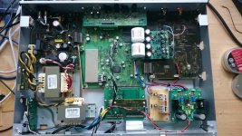
Attachments
a bottle of deodorant spray or toilet spray upside down works great too, spray directly on the components and pray (spray and pray)Now I got the cooling spray. I tried it on the IC where I put the screw on. No success. After that I tried the screw again. No success. Now the device is in the fridge again. If it starts after that again it will be very hard to locate the problem. Really bad because if the device starts it is a really good unit. 🙁
I'm still searching but I come more and more to the conclusion that it is randomly appearing problem. At the moment I've focussed at the power switch board. If you press the main switch the board were the switch is soldered is beeing bent a bit and directly in the bent there are two resistors R440 & R441. If the bard is bent they are stretched. I have to check the plans. Don't know if these resistors are importand. I thing the influence the key signal so that you need them in the line. Only crossing the switch with a cable das have the same effect but the device does not boot. So I think I need the circut. I tried some ice spray as well on this board and hat the impression that there could be the temperatur problem. I soldered all the pins on that board but no success. Sometimes it starts sometimes not. Having a problem with the bent board would also fit to my observation that the unit sometimes boots up if I press the switch with some more preasure. So investigation goes on 🙂
If it starts up after the freezer then you could start blowing warm air on it with a hot air gun via a narrow nozzle working from one side towards the center. It may be possible that you will find tha area what causes the failure after being warmed up.
1. disconnect CN205 checking the STB voltage(pin3 and pin 7). It should be 5 volt (very stable) even add load.... like car light bulb. If it is not 5 volt, you need check the switch power supply.
2. If it is not the problem from SMPS, disconnect CN202/CN203 and connect the power transfomer to AC then check the ACWP for 5volt and v+12 volt( it can up 14~15volt because of no load).
3. If everything okay, then you need to check other board.
2. If it is not the problem from SMPS, disconnect CN202/CN203 and connect the power transfomer to AC then check the ACWP for 5volt and v+12 volt( it can up 14~15volt because of no load).
3. If everything okay, then you need to check other board.
So, I did what you explained. The following observation:
Disconnected CN205: Pin 3 & 7 around 5V (didn't put load on)
Disconnected CN202/CN203 and connected the power transformer to external AC
Checked Pin 9 on CN205 (ACWP or one leg of ZD251): only around 1V, checked Pin 15-19: around 15V
But.., after that I connected the normal power supply cable (connected CN205 again) and fired the transformers with external AC as it was before. First try to start via main switch had no affect. Second try led to normal operation of the device.
Any idea to this behaviour?
oh no! You shouldn't connect cn205. It appears there is short on CN3001 or CN205 side.
check D251,D252,BD251, BD252,and c253
*Checked Pin 9 on CN205 (ACWP or one leg of ZD251): only around 1V, checked Pin 15-19: around 15V
In this part only 6 components, it it easy narrow down the failed component or bad solder joint.
D251, D252 and R253 will be the first to check then ZD251,c255 and r254
I think I got it. There is a NTC 3D15 in line to the fuse and this goes via a transformer to the switching IC FM260N. This NTC prevents from high current in case of switching on the device. In cold state it does not transmit very well, so that the IC is prevented for high current. This NTC does have a problem and only if I cool down the NTC the device starts. Clear because only in this state it prefents the IC from high current. I think I have read about the FM260N that there is a mechanism to go in prevention mode in case of a problem. Sometimes the NTC works and the IC works as well (after the device has been in the fritch or after cooling down the NTC 3D15). I bought a new NTC and will keep you updated. Thanks so far.
I still believe the Pin 9 of CN205 which need 5 volt when you disconnect from CN205/CN3001. This pin's name ACWP( AC Wake Up) which provides 5 v and let microprocess bootup.
I am pretty sure I know what's causing the problem... re-read my initial post that explains the principle of operation, and it will all make sense. You can confirm the exact issue if you measure the voltages during the start-up... with the help of the MIN / MAX function.
EDIT: I had to combine p64&65... to see the whole picture. Here it is 🙂

EDIT: I had to combine p64&65... to see the whole picture. Here it is 🙂
Last edited:
Thank you for your effort. And how does it explain the behavior at different temperatures? Cool - device starts; room temperature - device hangs (most of the time). At the moment I believe in a defect at TH201 (NTC3D15). If I'm cooling down this device with a cooling spray the unit boots up.
I never measured 5V on this pin but the device came up from time to time. If I cooled TH201 it started. If I put the hole device in the fritch it started. If I tried to start it at room temperature most of the time it failed. After pressing the main switch several times sometimes it started also at room temperature. So I'm really thinking of a current peek that is not prevented by TH201. Let's see what happens if the replacement part is inserted. 🙂I still believe the Pin 9 of CN205 which need 5 volt when you disconnect from CN205/CN3001. This pin's name ACWP( AC Wake Up) which provides 5 v and let microprocess bootup.
Thank you for your effort. And how does it explain the behavior at different temperatures? Cool - device starts; room temperature - device hangs (most of the time). At the moment I believe in a defect at TH201 (NTC3D15). If I'm cooling down this device with a cooling spray the unit boots up.
These parts are missing...?? Right??
What is the voltage at IC201, pin 5 when the unit starts okay vs. when the unit does not start okay?
The following conditions:
Now back in the living room with 25° and the device does not start
- pin 5 during starting process - no change, still 0-0,35V
After unplugging the AC cord for half a minute (no cooling with ice spray) it starts again.
It seems that if the ac power cord is plugged for some time something wents wrong. Over the night there was no AC on TH201.
What do you mean with missing parts in #58?
- 8 hours off and AC plug not in for this time
- room temperature about 20° because the device was downstairs in my workshop
- device started directly (pin 5 on IC201 went from 0V to 0,35V during starting phase)
Now back in the living room with 25° and the device does not start
- pin 5 during starting process - no change, still 0-0,35V
After unplugging the AC cord for half a minute (no cooling with ice spray) it starts again.
It seems that if the ac power cord is plugged for some time something wents wrong. Over the night there was no AC on TH201.
What do you mean with missing parts in #58?
- Home
- Source & Line
- Digital Source
- Pioneer N-50 power blue led blinking,unit is not booting up