How is the 12V? It would be funny if the relay contacts would be bad 🙂
Problem is my lack of time to look into the schematics.
Problem is my lack of time to look into the schematics.
Pin 15-19 to chassis ground 15V. Relais has been worked on with sandpaper at the contacts and contact spray. Looks good. Trafos were powered from external AC. Same behaviour all the time. At about 20° with AC unplugged for a while it starts. At 25° also AC unplugged for a while it never starts. I ordered FM260N now but this will take up to 4 weeks (Aliexpress).
That +5V STB rail is used extensively inside the whole unit.... even for USB-powered devices and for LAN IC's. It might be worth checking if you have anything plugged into the USB port.
I did not expect that the new NTC was going to make any difference. There might be some current limiting happening inside that IC.... or somewhere else...
You'd need to capture the voltages when the unit powers up okay vs. when it fails.
You still may have a cold solder joint somewhere... I explained this in one of my previous posts... and asked for well-lit, in-focus, high-quality photos.
I would try with an external source of +5V _STB... if I were you...because you either have current limiting inside that IC (DIL8 is insufficient for long-term reliability... I suggested a little heatsink on top), or a cold solder joint; a circular crack around one of the pins... that contracts when cold and provides good contact, but then expands when hot and causes a high contact resistance -> and the subsequent drop in current. So yeah, you will get +5V _STB ... but it might not be of sufficient current capability to deliver what's required when the unit is hot.
... if you want to see where that +5 V is used, search the schematics for V+5R0_STB, V+5R0_ST and V+3R3_ST. All of these points are supplied by that SMPS. Just keep in mind that each full page of the schematic diagram consists of 2 x A4 pages in the PDF... a pain!! I'd combine the relevant A4 pages into a single A3, and then print all A3 pages.
Good luck
Good advice. Simple to execute too and one of the first things one would do really if the 5V is suspect.
alochter, sanding relay contacts is often EOL for the relay. Old fashioned practice for large power relays in the past. If it needed sanding it was kaputt.
alochter, sanding relay contacts is often EOL for the relay. Old fashioned practice for large power relays in the past. If it needed sanding it was kaputt.
Last edited:
Thank your very much for all good support. I will replace the IC and if this does not help I'm done. Maybe there is less current somewhere or a cold solder joint (but I already soldered a lot of the board again). Nevertheless, mainwhile too much effort for a device I'm not really often using. Keep you updated.
Last edited:
That effort should be viewed in context "can I fix it or not?".Nevertheless, mainwhile too much effort for a device I'm not really often using.
Usability wise - buy yourself some bluetooth receiver and stream to it from your tablet or phone whatever you want. These N-50 type network players (of which I own one and still keep in living room) are already extinct dinosauroses 🙂
IC exchange does not fix the problem. So I'm done. Sometimes the device comes up, sometimes not.Thank your very much for all good support. I will replace the IC and if this does not help I'm done. Maybe there is less current somewhere or a cold solder joint (but I already soldered a lot of the board again). Nevertheless, mainwhile too much effort for a device I'm not really often using. Keep you updated.
Sorry to read this. Just do not throw the player into dumpster - it can still be a useful spare part donor.So I'm done.
It looks like a bad connector or losing wires. Every time you change the amp loction or disassemble / assemble the boards, the amp maybe works or not work.
Hello friends! I read all the posts and I guarantee that it was really cool to see how passionate we are about technology and how much we like our audio components. I have the same problem as you, and here in Brazil we have had intense summers. My N-50 also had the problem of not starting after a few seconds of the blue LED on the ON/OFF button blinking. Pioneer should provide more support, even with discontinued equipment, which does not have a similar product from the same brand. In any case, please do not discard your equipment. I'm also going to start some research and start spending time trying to find the problem. This is now personal!!! I don't know what the end of the story will be, but my N-50 looks new and I always leave it on so my wife can listen to her radio. I will do my best to find the defect and let everyone know! A hug and take care!

By the way, you guys left a lot of valuable info here; this will speed-up the diagnostics. Thank You!
Spambot?after replacing the chip everything was fine he had bad sectors
I just purchased one new in the box that's 12 years old, and I have the same problem. I would be looking at electrolytic caps and degraded connections first. These things were made in China where there's a ton of junky electrolytic capacitors.
Since I bought this thing new, I expect to return it for a full refund!
It's disappointing because you can't get a network player for under $1000 unless you build one yourself with PC parts.
Since I bought this thing new, I expect to return it for a full refund!
It's disappointing because you can't get a network player for under $1000 unless you build one yourself with PC parts.
Is that really so?It's disappointing because you can't get a network player for under $1000
What about Yamaha WXC-50 and WXA-50?
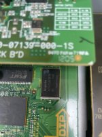
I have the same problem with my N30 where the Blue light keeps blinking slowly. I tried putting it in the fridge for a while and it booted up. I saw the post from herfrost and tried freeze spray on IC 1505(see Pic). I was able to get it to boot up consistently by cooling IC1505 down. I tried soldering The leads but that didn't work. The chip is available on eBay but my understanding is that this is flash memory and the firmware resides on this chip so I would not be able replace it without it being programmed first.
Attachments

Seems a goner. Too expensive or too much time loss/effort. Both possibly reasons to abandon and recycle. Maybe it will reincarnate
as a nice watercooker.
This is a thing to remember when it concerns defective Pioneer N-30 and N-50. Nasty error. Probably the main fault mode for these devices and obviously a hard one to fully diagnose as not many expect flash memory to die.
as a nice watercooker.
This is a thing to remember when it concerns defective Pioneer N-30 and N-50. Nasty error. Probably the main fault mode for these devices and obviously a hard one to fully diagnose as not many expect flash memory to die.
Actually flash cell charges fade in time. Some vendors even specify minimum data retention period for unpowered devices. But SSDs are designed to continually refresh their data when powered on. I do not know if simple flash storages do that. If not, it may be possible the charges drop below noise level at normal temperature, and cooling the chip down makes the data become readable again (for a while).as not many expect flash memory to die
OK but this audio player is one of the few where this happens like that and such in a relatively short time. Tried a few dozen and never had any of them failing. Apparently bad sectors in these Pioneers. From what I see when looking at secondhand websites is that they all seem to die. Maybe because of a programming imperfection or specific issues like high internal temperature or too high supply voltage!? Who knows. I have videoplayers that write updates on a two day or sometimes every day interval to emmc and they don’t have issues in years. In fact I have never seen this since a long time (except with SSDs and of course USB flash sticks).
And I suppose this device reads way more than it writes to flash. Strange issue.
And I suppose this device reads way more than it writes to flash. Strange issue.
Last edited:
- Home
- Source & Line
- Digital Source
- Pioneer N-50 power blue led blinking,unit is not booting up