5.4k 15k 10ohm
I was just about to say that I think it's bad, as it outputs the voltage that gets to pin 6 indeed, 0.3 but on the datasheet it says that the input voltage should be 30v. It's only 15v. It's being feed by a 7915 regulator which seems to work allright. Or I'm I being mistaken?
I was just about to say that I think it's bad, as it outputs the voltage that gets to pin 6 indeed, 0.3 but on the datasheet it says that the input voltage should be 30v. It's only 15v. It's being feed by a 7915 regulator which seems to work allright. Or I'm I being mistaken?
It could be defective.
The max input is 30v but the actual input only has to be a few volts about the rated output voltage.
As a side note, use as few NTE parts as possible. For voltage regulators, they're not a real risk but they're expensive and you never know precisely what you're installing like you do when you buy the original parts from a reputable distributor.
I'm using RS Components and TME for parts. RS Components is one of the biggest over here in the UK, and TME is from Poland and is well known in most of Europe.
You reckon that the other differences in voltage could be due to this one? I'll probably find out after replacing the regulator.
Also, seems odd to me, to have the same 2v voltage on the source and gate of the high side FETs. One step at a time or this could be something else?
Also, seems odd to me, to have the same 2v voltage on the source and gate of the high side FETs. One step at a time or this could be something else?
The IC won't function without the -5v. No voltages that you read on the output drives are relevant.
Right, ordered the IC. Will update further after I've replaced it. Thank you so much for your time again.
IC has been replaced. I have drivewave, not that clean but allright.
Now, if I don't attach any load, using my 2A power supply, the rail builds up to around 54v and the amp goes to idle. When I'm attaching a small speaker, I don't care about the speaker if it gets damaged, it's a old oem speaker almost gone anyway, after entering idle state, speaker gets some DC voltage and the rail voltage starts going up. I removed the power at around 102v. Was still going up. No sound output, I applied some input signal.
Any thoughts?
Positive AND negative 102v or only positive OR negative rail?
IF you insert a 100uF non-polar cap in series with your test speakers, it will protect them from DC.
How much DC do you measure with your meter?
IF you insert a 100uF non-polar cap in series with your test speakers, it will protect them from DC.
How much DC do you measure with your meter?
This is common where the drive circuit for one half of the output is damaged.
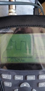
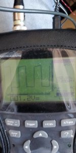
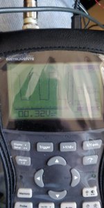
Post a photo of the drive signal that you said wan't quite right.
Post a photo of the drive signal that you said wan't quite right.
1 is from positive drain
2 from positive side gate
3 from negative side gate
Negative side source is changing it's shape. Going from normal to smaller then normal again.
Transformer has a high pitch sound when going to idle, that wasn't there before. It's changing frequency when probing FETs.
2 from positive side gate
3 from negative side gate
Negative side source is changing it's shape. Going from normal to smaller then normal again.
Transformer has a high pitch sound when going to idle, that wasn't there before. It's changing frequency when probing FETs.
Attachments
Is this scope fully isolated from the mains?
When you post photos, take them from an angle that doesn't have a bad reflection like these. This applies to scope and board photos.
When you post photos, take them from an angle that doesn't have a bad reflection like these. This applies to scope and board photos.
I tried but at the moment I was trying to hold the scope and probe as well, trying to take the picture in the meantime.
It runs on it's own power supply from the mains, can run on battery as well. But I do have to use the ground from the probe to be able to have proper readings, so I assume it is.
It runs on it's own power supply from the mains, can run on battery as well. But I do have to use the ground from the probe to be able to have proper readings, so I assume it is.
I want to see the drive waveforms on the outputs. I would prefer if you were running from batteries.
Solder a resistor leg to the gate leg and the source leg of the outputs (one FET per bank). Clip the probe to the gate and the ground clip to the source. This will free your hands.
Set the scope so that the waveform (3-4 cycles) covers the entire width of the screen. There is no need for the information on the right.
Well, I managed to burn the 2092 while probing some voltages. Was bound to happen at some point I guess. I have another one ordered anyway along with some other parts, for a while, but that one is still not on stock, so I'll have to wait until it's delivered and be more carefull next time
Edit: just had an email that it will be delivered somewhere this week. They are watching me 🙂)
Edit: just had an email that it will be delivered somewhere this week. They are watching me 🙂)
Last edited:
While you're waiting, pull the IC and confirm that all of the regulated voltages are still there.
Did you check the outputs after the IC failed?
Did you check the outputs after the IC failed?
Something got damaged as well, as it is still in protect after I removed the IC. Trying to determine what. It doesn't build rail voltage at all just goes to protect. Power supply is fine, removed the diodes to be certain.
Outputs might be gone as well as they read short on every pin. Removing them now.
Yes, couple of the outputs are gone as well....
This is the most stubborn amp from the bunch. I had 3 of them. Small one, had only the output fets to replace. A Bassface db1.2 that required a complex repair as well and this one. The bassface might still have something, not sure about it, it outputs sound, but the negative side fets are getting hot quite fast. In about 30 seconds. Test was made with the small power supply and same small speaker I'm using to test this one.
This one, the Pioneer, was the most damaged one since I bought it though, so if I manage to repair it, I'll be quite happy.
Last edited:
Allright, moving on. Replaced the 2092, replaced the output fets, replaced some dead resistors around the 2092, some transistors as well.
The amp builds rail voltage and idles fine if left alone.
When adding the speaker, it goes to protect and dumps all the rail to the ground I believe, as it starts building it again. It doesn't do it all the time, sometimes it will stay in idle with the speaker but sends about 1v of DC to it. And no sound output as well. Also, the output inductor, which is pretty solid, gets pretty warm. Removed it, tested it with the ESR meter, is being detected as a inductor but with a value of 0.04mh, which seems pretty small for me.
Anything else I could check based on this behaviour?
- Home
- General Interest
- Car Audio
- Pioneer GM-D9601