Hello everybody.
My knowledge of electronics isn't that high but I'm learning. Fixed other amps before but I've only recently took it to the next level and learned about rail voltages and bought an portable osciloscope. That being said, I'm taking on the power supply first as it had problems and I also managed to short pins 7-8 on the TL494 and I think that one of the transistors went as well, as now I lost even the power I had on the chip. Ordered a set of transistors, I was just wondering if anyone knows what power I should read on the pins of the TL494 and how can I calculate it myself? Also, the FETS are being driven with 5V? As before the short, I had 5V on one bank and about 2.8 on the other, which I believe it was due to another faulty transistor as well. Thank you
My knowledge of electronics isn't that high but I'm learning. Fixed other amps before but I've only recently took it to the next level and learned about rail voltages and bought an portable osciloscope. That being said, I'm taking on the power supply first as it had problems and I also managed to short pins 7-8 on the TL494 and I think that one of the transistors went as well, as now I lost even the power I had on the chip. Ordered a set of transistors, I was just wondering if anyone knows what power I should read on the pins of the TL494 and how can I calculate it myself? Also, the FETS are being driven with 5V? As before the short, I had 5V on one bank and about 2.8 on the other, which I believe it was due to another faulty transistor as well. Thank you
power I should read << you measure/read voltage, not power on the terminals/pins of the IC.
The voltage on the various terminals of the 494 can be greatly varied and everything be perfectly fine. What's critical is that you have supply voltage on pin 12 and ground on pin 7. If you have those, you should have 5v on pin 14.
The FET gates are driven with a pulsed DC. It will often read about 5v with a multimeter but readings from just over 0v to 6 or 7v are possible when reading DC voltage. A scope is far better to check the gate drive.
You likely blew a transistor in line with pins 8, 11 and possibly 12. You will have to follow the circuit back to find the transistor.
Yes, voltage. My bad, wrong choice of words. Indeed, I've followed the trace to the closest transistor and it seems to be the culprit. Before this it had almost 12V. I'm using a small adapter that delivers 12V with about 2A to be safe. I was reading 11.98 or a bit lower in most places and not sure if the voltage loss was allright taking the fact that the gate FETs were removed and the rectifiers as well. Basically, I was only powering the driver circuit. I should have some driver transistors tomorrow and continue from there. Thank you so much for your input at the moment.
So, replace the faulty transistor and the chip is back to life. I have the rectifiers and power supply fets removed and I have like this: voltages on the chip pins, I'm going to put them in order starting with number 1... 3.71v 5.01v 0.11v 0.15v 1.59v 3.46v 0v 11.55v 4.48v 4.47v 11.56v 11.56v 5.01v 5.01v 6.94v 5.01v. I'm using a small 12v adapter with about 2A for powering it up. Now, some of the things I'm not sure about. The D702 which is before the the chip, lowers the voltage down from 12.20 to 11.59v seems weird to me. Drain on the FET's is 12V but the gate is 0.5v on one bank and 4.38v on the other. Pretty sure something else blew up when I shorted the pins as the one with 0.5v used to have about 2.38v or something like that. Some guidance would be much appreciated from this point. Pin 5 has the sabertooth oscilation. Thank you
When you post, break the various topics with a blank line. It makes it MUCH easier to read.
When you list the voltages on an IC, do so vertically, using a colon and a space. like this
Pin 1:
Pin 2:
Pin 3:
Pin 4:
Pin 5:
Pin 6:
Pin 7:
Pin 8:
It's virtually impossible to have different voltage readings on the drains for the two banks. They are directly connected to the B+ supply through the large windings of the power transformer.
For the diode voltage drop:
Diodes
You had lower voltage readings on the gates before because the rail voltage had reached it's target voltage and the duty cycle had rolled back. The actual peak voltage was the same as you would see on a scope but the lower duty cycle makes a multimeter read lower.
Ah, fair enough. My bad with the topics. I'm used to write a lot in little space I guess ") ) wasn't sure about the diode at first but everything seemed allright with the readings so I thought it is just a case of a normal voltage in the end. Been away for a while, will get back to it now to check and replace the other transistors that probably died in the first place.
) wasn't sure about the diode at first but everything seemed allright with the readings so I thought it is just a case of a normal voltage in the end. Been away for a while, will get back to it now to check and replace the other transistors that probably died in the first place.
) wasn't sure about the diode at first but everything seemed allright with the readings so I thought it is just a case of a normal voltage in the end. Been away for a while, will get back to it now to check and replace the other transistors that probably died in the first place.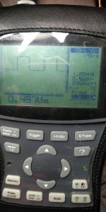
'Channels' are generally used to refer to the audio channels, not power supply. The power supply has 2 'banks' per transformer for push-pull power supplies.
Output of the transistor?
When you post a waveform, you need to post where the two probes were, precisely. This means giving the terminal name and the circuit board designation. When there is no diagram available, you should post a photo of the area of the board involved.
Output of the transistor?
When you post a waveform, you need to post where the two probes were, precisely. This means giving the terminal name and the circuit board designation. When there is no diagram available, you should post a photo of the area of the board involved.
- Status
- This old topic is closed. If you want to reopen this topic, contact a moderator using the "Report Post" button.
- Home
- General Interest
- Car Audio
- Pioneer GM-D9601