Are you going to get a chance or not? If you are, there's no point in him answering my post. If you don't know, how long does he wait to see if you will get a chance?
Sorry Perry I was typing that when you had posted.
Here are the numbers as per Perrys instructions besides pin 13 which is taken from negative rail.
1- 4.98
2- 0
3- 0
4- .049
5- 0
6- -4.90
7- 5.160
8- 5.169
9- 0.03
10- 0
11- 5.7
12- 12.0
13- 36.6
14- 0.4
15- 0.4
16- 3.6
This is at 12v using a Fluke 87 and no signal in.
Do not slip the probe ends and try to use a leading capacitor or resistor pad if you can.
Last edited:
I was wondering about the -5 but you edited it.
Why 13 from the negative rail? It's floating along with 14 and 15?
15 should be about 11v above 13 and 14 should be between 13 and 15.
Is this amp working? I see no high-side drive.
Why 13 from the negative rail? It's floating along with 14 and 15?
15 should be about 11v above 13 and 14 should be between 13 and 15.
Is this amp working? I see no high-side drive.
I don't have the exact numbers but if you post the voltages (copy and paste numbered list), I'll see if I see anything obvious. For pins 1-6 and 16, black probe on secondary ground. For pins 7-12 black probe on the negative rail. For pins 13-15, black on pin 13.
Pin 1:
Pin 2:
Pin 3:
Pin 4:
Pin 5:
Pin 6:
Pin 7:
Pin 8:
Pin 9:
Pin 10:
Pin 11:
Pin 12:
Pin 13:
Pin 14:
Pin 15:
Pin 16:
Because I would get a zero reading with both probes on the same point as per your directions to the OP. I can take 13's reading any way you would like.
Yes this amplifier is complete.
I can double check the HO and LO if you would like.
Pin 14 is 5.56v
I must have not been on the pad fully. It is a tight area to get readings with a DMM.
I must have not been on the pad fully. It is a tight area to get readings with a DMM.
Bare with me, as my black probe is connected to the other via a crocodile clip... Don't know if you use the same name for it back there 😀 measuring now.
Mine reads like this as per instructions:
Pin 1: 4.70
Pin 2: oscilates between + - but around 0
Pin 3: oscilates betwen 0.174 and 0.5
Pin 4: 0.37
Pin 5: 4.62
Pin 6: 0.2
Pin 7: 5.07
Pin 8: 5.07
Pin 9: 0
Pin 10: 0
Pin 11: 0
Pin 12: 11.82
Pin 13: 0 with negative on same pin
Pin 14: 0
Pin 15: 10
Pin 16:6.42
Pin 1: 4.70
Pin 2: oscilates between + - but around 0
Pin 3: oscilates betwen 0.174 and 0.5
Pin 4: 0.37
Pin 5: 4.62
Pin 6: 0.2
Pin 7: 5.07
Pin 8: 5.07
Pin 9: 0
Pin 10: 0
Pin 11: 0
Pin 12: 11.82
Pin 13: 0 with negative on same pin
Pin 14: 0
Pin 15: 10
Pin 16:6.42
Last edited:
If I'm following the trace I end up to the 1GM transistors that read 5v on the other side.
Last edited:
'IF'? Only you can tell us what we need to know.
I don't have the 9601 diagram. I'm working off of the 9605. In this amp, the -5 comes from a 7905 regulator.
I don't have the 9601 diagram. I'm working off of the 9605. In this amp, the -5 comes from a 7905 regulator.
When? Sorry for my english 😀 not that perfect
On mine, that pin goes up to that KIA7812A regulator that I've now replaced with a NTE1970 which was the recommended equivalent. It has 18.63v on one side and 12.20v on the other side
On mine, that pin goes up to that KIA7812A regulator that I've now replaced with a NTE1970 which was the recommended equivalent. It has 18.63v on one side and 12.20v on the other side
Last edited:
Unfortunately no. Best thing I've had was the 9605 that you posted in another thread, and that helped me a lot with the power supply. Audio stage is different though.
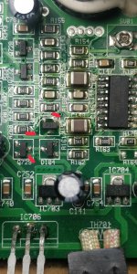
Trace goes to that 10 ohm resistor, continues to the 10k resistor and then to the 1GM transistor. Also, underneath, before the 10k resistor it also goes on the other side of the transistor. Then continues to the voltage regulator. It also goes into a CJ79L05 which is a negative voltage regulator. I assume my problem could be over there somewhere, with one of the capacitors maybe.
Attachments
Last edited:
- Home
- General Interest
- Car Audio
- Pioneer GM-D9601