So, the IC does get hot it seems. Readings were in the range of 1.1k
If I measure the voltage on the regulator with the black probe on it's ground I have 41.2 on the input and 42.4 on the output.
I can assume both of them are gone as well. I'll order them along with driver transistors as well.....
Anything else I could check in the are while I'm at it?
If I measure the voltage on the regulator with the black probe on it's ground I have 41.2 on the input and 42.4 on the output.
I can assume both of them are gone as well. I'll order them along with driver transistors as well.....
Anything else I could check in the are while I'm at it?
Were you able to find the original driver transistors from a reputable distributor?
Are you sure the drivers failed?
Check all of the low-value resistors in and around the area between the driver IC and the outputs.
Are you sure the drivers failed?
Check all of the low-value resistors in and around the area between the driver IC and the outputs.
No, not really. Actually I couldn't find them anywhere. Only replacements.
I'm just assuming, though it's behaviour seems to be allright.
I'm just assuming, though it's behaviour seems to be allright.
Well, it's been a while, as I've been in holiday. I hope everybody is safe from the damn virus.
As for the amp, I'm about to give up. Seems to go from bad to worse.
I've replaced that KIA7812 regulator and the driver transistors and now and can't get it to idle even with the bigger power supply. Rail voltage goes up to about 40V and that's about it. Also, measured on the speaker terminal, now I seem to get even 12v DC at times. It's probably time for somebody that know what he's doing better than me.
12v DC at the speaker terminals could mean that the power transformer is shorted primary secondary.
What's the resistance between the B+ terminal and the secondary ground.
Try twisting the transformer to see if that value changes.
What's the resistance between the B+ terminal and the secondary ground.
Try twisting the transformer to see if that value changes.
I have removed the transformer at the early stages of the repair, when I was doing the power supply. Transformer is allright.
I'm getting about 90k resistance.
Twisting doesn't affect it.
I'm getting about 90k resistance.
Twisting doesn't affect it.
It'a not plain 12v, it's somehow rising while it's trying to build rail voltage.
What I'll do, is remove the rail capacitors, as it has plenty, maybe leaving only one each side. This should help see where it drops everything and giving me the option of using only the small power supply.
What I'll do, is remove the rail capacitors, as it has plenty, maybe leaving only one each side. This should help see where it drops everything and giving me the option of using only the small power supply.
That's time consuming and many snap-in caps won't easily come out without damaging the vias.
Can you easily remove the 2092?
Can you easily remove the 2092?
I know but it would help me a lot probably, as for the time, I'm learning anyway and as you can see, I've spent a lot until now. I don't have a specific timeframe. But I do agree about the damage.
I do have a hot air work station, so yes, I can. What can I expect by removing that?
I do have a hot air work station, so yes, I can. What can I expect by removing that?
Hot air is likely to cause more problems than an iron.
It will allow you to check several things and knowing that what you find isn't related to a fault with the IC.
If you remove it, go through the procedure that you previously have to see if anything has changed.
It will allow you to check several things and knowing that what you find isn't related to a fault with the IC.
If you remove it, go through the procedure that you previously have to see if anything has changed.
Well, it seems that the 2092 was dead allright. Removed it and most of the readings are open line. Now the amp builds the rail and goes to idle only with the small 2A power supply.
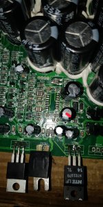
The capacitor marked in the picture was getting hot. I presume it will be out of value but I've ordered myself a ESR meter that measures capacitance, diodes and some more. It was needed anyway.
Pins 7 and 8 are connected to a 0 ohm resistor? That seems pretty odd for me. It does say 000 on it. I don't really see a point but then continues to a missing resistor. I've seen that recently. That resistor was missing since before me having the amp so I'm not certain if it's not needed or somebody else removed it prior in me buying the amp.
The drain on the fets still has about 1.8v with them removed and should be 0 as far as I know. I'm guessing something still leaking to ground maybe.
Attachments
That was the only thing I thought myself. Thank you for confirming the missing resistor. I was unsure about that.
Well, I have changed the 2092 and added one FET to each bank. Still nothing. The 2092 is good now. No wave though.
Another problem, all the op amps are supplied with 30V instead of their normal supply voltage which I guess should be around 15-18v. Can't find anything wrong in the circuit though. I I'm not sure the input signal goes were it should in this case.
Another problem, all the op amps are supplied with 30V instead of their normal supply voltage which I guess should be around 15-18v. Can't find anything wrong in the circuit though. I I'm not sure the input signal goes were it should in this case.
That if I measure from the ground of the op amp. If I measure from the main ground is about 15.
Even so, no drive on the output fets. With the fets removed, I have about 2v on the drain, on the low side, and the same 2v on the high side on both gate and source
Even so, no drive on the output fets. With the fets removed, I have about 2v on the drain, on the low side, and the same 2v on the high side on both gate and source
So, the supply voltage of the 2092 is about -42 or something like thay. One of the reasons I have nothing. I'm guessing it's a diode probably between other things...
The picture you last posted is the area of the voltage regulators. Make sure the regulators have the proper output voltages present. Keep in mind that you have positive AND negative voltages. This is where scopes come in handy to see the positive and negative voltages in reference to the grounding point.
I am not sure if you have done this or not, but read up on the datasheets as much as possible so you have an idea of what you are looking at.
You will have no output if the amplifier is seeing any protection conditions.
I am not sure if you have done this or not, but read up on the datasheets as much as possible so you have an idea of what you are looking at.
You will have no output if the amplifier is seeing any protection conditions.
Voltage regulators have already been checked, the one that was bad has already been replaced.
Not sure what kind of voltage should the 2092 have in this application but I'm pretty sure it shouldn't be what I've seen. I have negative voltage on the VCC pin. That's why I'm thinking something is bad over that area as well.
Not sure what kind of voltage should the 2092 have in this application but I'm pretty sure it shouldn't be what I've seen. I have negative voltage on the VCC pin. That's why I'm thinking something is bad over that area as well.
I don't have the exact numbers but if you post the voltages (copy and paste numbered list), I'll see if I see anything obvious. For pins 1-6 and 16, black probe on secondary ground. For pins 7-12 black probe on the negative rail. For pins 13-15, black on pin 13.
Pin 1:
Pin 2:
Pin 3:
Pin 4:
Pin 5:
Pin 6:
Pin 7:
Pin 8:
Pin 9:
Pin 10:
Pin 11:
Pin 12:
Pin 13:
Pin 14:
Pin 15:
Pin 16:
Pin 1:
Pin 2:
Pin 3:
Pin 4:
Pin 5:
Pin 6:
Pin 7:
Pin 8:
Pin 9:
Pin 10:
Pin 11:
Pin 12:
Pin 13:
Pin 14:
Pin 15:
Pin 16:
The IRS2092 will have several voltages present (even rail voltage) as you can see from the application diagram that is provided by IR.
You may see that negative voltage on pins 7, 8, 9 and 10 based on the application diagram keeping in mind voltage drop across any resistors.
If I get a chance to make some room on the bench I can get you some numbers but they won't be exact as my supply voltage may be different than yours which will give different rail results.
- Home
- General Interest
- Car Audio
- Pioneer GM-D9601