As a matter of interest I decided to lash up a circuit to boost the current through the Green LEDS. I took AC of the heater and recified it with a fast soft recovery diode. I put it through some capacitance and a LM7805 and then some more capacitance. I then put it through a 330R resistor and finally the LED with a 22uf bypass cap. This gives a final current of 13mA through the LED.
The result is very good, very clear and detailed with plenty of bass. Difficult to say exactly whats what as the bias point has shifted slightly. Still it works. All the previous softening and smudging has gone. Got a bit of hum and don't need the extra gain so don't know if I will keep it, but I think it sounds better than a plain unbypassed resistor.
Shoog
So when I look for the right Led,if I want 1,5 v at the catod and 15mA current I look at the Led´s Forward current/volt and find one that crosses at 1,5v/15mA? Is that right?😎
Seccond question-Does anyone have a schema for a CCS for the anode
or can make one? 🙂
Seccond question-Does anyone have a schema for a CCS for the anode
or can make one? 🙂
Take a look at the CCS I used in the thread "SY gets jiggy" for a good example of an inexpensive plate CCS that works very well.
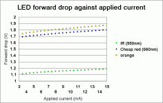
The LED "curves" take off pretty sharply at a particular voltage rather than being a smooth curve. So look for a color with a Vf near the bias point you want, which will generally be specified at 10mA; there won't be a lot of difference between 10 and 15mA.
The LED "curves" take off pretty sharply at a particular voltage rather than being a smooth curve. So look for a color with a Vf near the bias point you want, which will generally be specified at 10mA; there won't be a lot of difference between 10 and 15mA.
Hi Shoog, have you tried bypassing the LED with a cap yet? In my measurements the green LED benefited most from it, dropping all harmonics below the noise floor of the sound card and besting both the red and the yellow. Curious whether it makes an audible difference for you. On the bench it took at least 25uF to reach maximum benefit and 6.8uF made little difference. The bypass occurs in the midrange for these values so theoretically it possibly alters the stage frequency response to some degree. How much depends on the degree of degeneration caused by the LED I suppose.
"Hi Shoog, have you tried bypassing the LED with a cap yet? In my measurements the green LED benefited most from it, dropping all harmonics below the noise floor of the sound card and besting both the red and the yellow. Curious whether it makes an audible difference for you. On the bench it took at least 25uF to reach maximum benefit and 6.8uF made little difference. The bypass occurs in the midrange for these values so theoretically it possibly alters the stage frequency response to some degree. How much depends on the degree of degeneration caused by the LED I suppose."
I did bypass the Green LEDs with 22uf, but this was more to do with generating a stable 9mA current boost than bypassing audably. Can't say if it has effected the sound as I have nothing to compare it with really. I have been sufficiently impressed with the boosted current version that I have kept it in my preamp. Overall there is a significant amount more detail across the whole audio range compared to an unbiased cathode resistor. Got rid of all residual hum and shifted the bias points to compare more with the original version.
Well worth the effort.
Shoog
Can somebody please explain this to me.
Last night when playing music, I observed that both the orange LEDs are flashing at a regular interval. After a while, the flashing stoped. I turned my record to the other side, played it and the flashing starts again. When playing the middle part of the record, the flashing stops.

When I investigated, the record that I'm playing has a horizontal warp at one point. When the cart hits that point, it must be banging left and right on the vinyl groove and during this, the LEDs flashes.
What the??
Hey ryssen, tubelab has a nice schema of the 10M4 IXYS CCS as an alternative to that of SY. They're cheap and I'll be ordering a couple from RS Components. Pete Millet has also experimented with them, with positive outcome.
Last night when playing music, I observed that both the orange LEDs are flashing at a regular interval. After a while, the flashing stoped. I turned my record to the other side, played it and the flashing starts again.
 When playing the middle part of the record, the flashing stops.

When I investigated, the record that I'm playing has a horizontal warp at one point. When the cart hits that point, it must be banging left and right on the vinyl groove
 and during this, the LEDs flashes.
What the??
Hey ryssen, tubelab has a nice schema of the 10M4 IXYS CCS as an alternative to that of SY. They're cheap and I'll be ordering a couple from RS Components. Pete Millet has also experimented with them, with positive outcome.
The brightness change is an indication that you're clipping that stage.
Another nice benefit of using a LED, a built-in distortion monitor!
Another nice benefit of using a LED, a built-in distortion monitor!
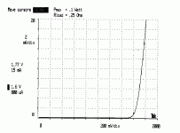
EC8010 said:And this illustrates how sharply LEDs take off. It's the same red LED in all three attachments.
I was about to put together a test setup to make this curve when you posted this.
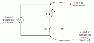
For anyone that wants to look at these curves themselves with different diodes, there's a really simple setup.
Attachments
That's what I was speculating, just not sure. Now I have a distortion monitor, and record warp indicator. Don't you just love LEDs!! 😀
I´ve been trying the tube with resitors (6C4) 100Ohm katod,10K anod
and I get 1,5 v at the katod,then trying some Led´s I have at home and I get 1,95 -2,2 volt at the catod,do I tweak the anod resistor to get right volt at the katod?
Did you bypass the Led? How big C?
and I get 1,5 v at the katod,then trying some Led´s I have at home and I get 1,95 -2,2 volt at the catod,do I tweak the anod resistor to get right volt at the katod?
Did you bypass the Led? How big C?
Hi ryssen, if you wanted 1.5 volts at the cathode, try the RED LED. I don't bypass mine. If you want to, just read the posts of rdf comparing unbypassed/bypassed characteristics.
Hi ryssen, arnoldc called it. Use a different LED to lower the voltage. In general the voltage drops with colours of longer wavelength (more red.)
SY calculated the effect of the LED's harmonics in the ~100 dB range on the output of a typical tube circuit so a bypass is far from an essential component. I played around a bit last night with the best performing sample of red on hand. The fundamental and second harmonic only were visible above the -125 dB noise floor of my test setup. A 33uF bypass completely elminated the 2nd. The fundamental on the other hand was little affected by values as high as 12,000uF. Without in-circuit testing (maybe this weekend) no one knows but best guess right now is that anything over 40uF will have no measurable effect at all. My recommendation would be to try 33uF and if you think it makes no difference get rid of it.
As always I reserve the right to be completely wrong until I know better.
Hi there,
Thanks for all your useful info!
I also tried this bias on the 6C45 driver stage in my 300B SE amp.
A yellow LED (without bypass) replaces orginal 130R cathode resistor & bypass cap and gives a perfect identical 2V bias as original.
The listening impression is the improved low level detail. The decay of piano sound is more fluid-like. Such charactor makes the sound & atmosphere more real.
Good mod!
I'm going to try this method on the 5842 pre. It needs lower bias on the lower B+. So I have to buy some IR LED for it....
Thanks for all your useful info!
I also tried this bias on the 6C45 driver stage in my 300B SE amp.
A yellow LED (without bypass) replaces orginal 130R cathode resistor & bypass cap and gives a perfect identical 2V bias as original.
The listening impression is the improved low level detail. The decay of piano sound is more fluid-like. Such charactor makes the sound & atmosphere more real.
Good mod!

I'm going to try this method on the 5842 pre. It needs lower bias on the lower B+. So I have to buy some IR LED for it....
Hi CLS, I highly recommend checking spec sheets first and look for the steepest forward current vs. forward voltage curves at the current of interest. Not all IR LEDs are better than reds. By chance in the junkbox at work I found a pair of antiquated Sharp VHS remote controls bravely willing to give up unmarked IR LEDs for the 6c45 front end of my amp. By appearance and voltage drop vs. current I strongly suspect they're Osram (formerly made by Siemens) SHF 484 or 485. The bias changed from ~1.4 to 1.1 Vdc, which is a obviously a factor (the tube is fed by a CCS so the current remained constant), but the improvement in sound quality wasn't subtle. If they're legit these are available on Ebay for under $0.50 each.
Good to know that yellows give exactly 2V
A quick review suggests the following voltage drops;
Red 1.7V
Green and Orange 1.9V
Yellow 2V
Blue 4V
Shoog
A quick review suggests the following voltage drops;
Red 1.7V
Green and Orange 1.9V
Yellow 2V
Blue 4V
Shoog
Hi,
Almost a year ago I replaced the r/c bias at the cathodes of my phonostage with IR LEDs (1.2V). The noise level went down a significant margin, overall sound was more 'relaxed' w/ less zippy highs. I guess largish value cathode bypass lytics (330uF in my case) at the input and 2nd stage do more damage compared to LEDs.
fred
Hi rdf,
Yes I checked the specs of the LED.
Maybe what I have on hand are very differently sourced from yours.
The yellow ones I have is spec'ed as 2.1Vf@20mA, while the red one is 2.2Vf@20mA.
So I tried the yellow first, and it worked perfectly. By the same bias voltage, the previous 130R resistor gave about 15~16mA.
Assumed it's the same current now with LED in amp, then it's below the spec'ed nominal current, thus slightly lower voltage should be reasonable.
------------
By the way, I got some IR LED yesterday & tried them on the 5842 pre.
I currently put ones of 1.28Vf@50ma in it. They give 1.1x~1.2xV @ 20-some mA, similar, but not perfectly identical operation point as the original.
They deliver similar sound charactor as in the 6C45 driver of 300BSE, very detailed, crystal clear.
My pre amp is actually a 2in/4out xover (2way stereo).
http://www.diyaudio.com/forums/showthread.php?s=&threadid=61037&perpage=10&highlight=&pagenumber=2
In the LPF portion, it's 2nd order RC with cathode feedback, so it seems I can not use LED here. (As I read previously in this thread, LED is low impedance at AC, I would lose the cathode feed back... )
Now LEDs are used on the HP portion only, about 160Hz & above.
The high definition charactor of mid-hi sound makes the system balance change a bit. It makes the original warm rich sound to a somewhat more analytic feel. Both my LED experiments are working in the same signal string, same frequecy range of mid to hi. So I supposed this would emphazise the effect one step further.
Pitty that this technique can not fit in the low frequency department in my system.
Oh, I also thought about those higher bias voltage applications. Can we just stack them up to the desire voltages?
This also make me think of the Axiom 300B with damping diodes:
http://home.att.net/~chimeraone/axiom300bschematic.html
Damping diodes vs LED, hmmmm.....
This also make me think of the Axiom 300B with damping diodes:
http://home.att.net/~chimeraone/axiom300bschematic.html
Damping diodes vs LED, hmmmm.....
- Status
- Not open for further replies.
- Home
- Amplifiers
- Tubes / Valves
- Ping Sy: LED for Cathode Bias


