It also wasn't intended to be negative, Bob.
Fun has no rules, it's whatever anyone makes of it.
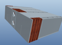
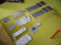
For completeness I felt to add for those who might consider a heat exchanger build themselves, that in most cases it's more expensive to DIY one, plus that the one as-is has several elementary flaws.
Fun has no rules, it's whatever anyone makes of it.
For completeness I felt to add for those who might consider a heat exchanger build themselves, that in most cases it's more expensive to DIY one, plus that the one as-is has several elementary flaws.
Bob,
If he being mean, just stomp his foot


Not a problem. I'm actually happy to learn custom sizes of that style of water block are available. Jacco, I used to buy lots of stuff from McMaster and will check it out.
Pass DIY Addict
Joined 2000
Paid Member
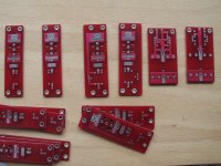
Hoping to build a B1 buffer next but I was wondering if anyone knows,
A) What is the input sensitivity of the A40 for full output,
B) Can the amps run with approx +/- 40V rails (my transformer secondaries are 25V and I have replaced the JFET with 2N4392,
C) Could the output stage bias be increased to 2 amps. My speakers are 4 ohms and the A40 will move into class AB at 20 watts into this load.
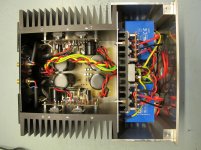
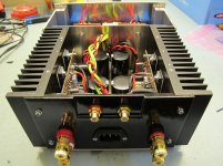
Earthloop, it's great to see a new a40 build! This was my first amp project - mainly due to the PDF that was available at the PassDIY website when I started. Most of my efforts for the a40 are documented here.
I can make a stab at some of your questions. I do recall measuring input sensitivity for the a40 at some point, but I cannot find where I made my notes. I tend to recall it take about 1.8v to hit full output. I have a clear memory of getting 52w into both a 4-ohm and 8-ohm resistive dummy loads.
As for increasing rail voltage, the only problem that I can see (and maybe I'm missing something) is that the 2N5248 FET is limited to 30v. Replacing this with higher rated part should prevent problems. I don't really see this as a problem for you, though. Your transformer has 25v secondaries, so you should only see rail voltage of about 35v. My transformer has 24v secondaries and I get ~32v rails...
Output bias can be adjusted as well. See the table at the bottom of my a40 page. I experimented with several values for R11 and the resulting bias level. I remember Nelson stating somewhere that the bipolar output devices are most linear and sound better when their bias is kept below 1.0A each. My amp is biased at about 3.2A per channel, so each output transistor runs at about 0.8A bias.
Overall, my A40 runs on 32v rails, 3.2A bias per channel, and produces a pinch more than 50w of output. The input sensitivity is greater than my Aleph-X amps and the a40 can comfortably drive my power hungry Avro speakers to satisfying levels in a large room. I think you'll be happy with yours when it is completed!
Eric
Originally Posted by buzzforb
Bob,
If he being mean, just stomp his foot
Jacco wasn't being mean, Buzz... he was just giving us his best AndrewT impersonation 😀
I'll have to try harder, you're still laughing.
(my left foot, please)
Wouldn't go that far. It was just an easy OT shot.
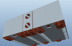
It's been a fun and funny morning, but I would also welcome some candid comments about the cooling technique itself. I'm going to play through at least to the next phase, but all comments both pro and con are welcomed and encouraged.
If this thread isn't exactly the proper place for the topic a new one could be started if there is any interest.
If this thread isn't exactly the proper place for the topic a new one could be started if there is any interest.
IMO bcmbob, this topic (and your efforts) DESERVES its' own thread. It would be more easily found in a search that way.
DM, Can you supply some information on the transformers you used. They are nice and compact which is a great idea for the ACA. I have a pair of Peter Daniels Universal PS boards that might be a good match for those tranis.
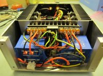
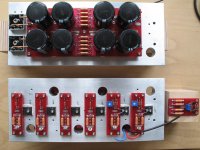
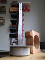
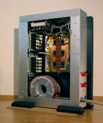
F5 turbo, with modular output stage (V1, V2).
Attachments

Last edited:
It's seems to me, it is a very nice project.🙂
You have chance to listen it soon.
I have been requested by PM to post another one.
Patrick
I am just browsing through the Pass labs forum. Some fantastic stuff here.
This one is stunning Patrick. What have you got the bias set at?
The case work . . . wow, what can I say. Did you do the machining yourself or get it done by a professional company?
Kudos!
🙂
Attachments
Last edited:
> This one is stunning Patrick.
Thank you. 🙂
> What have you got the bias set at?
1.3A per FET.
> Did you do the machining yourself ?
This particular one yes, most of it by hand milling.
The front panels and the Speaker terminals were done by CNC.
And I wrote the G-Code myself.
The F5X cases are now done by our own factory.
Cannot do all 30 sets myself by hand .....
Patrick
- Home
- Amplifiers
- Pass Labs
- Pictures of your diy Pass amplifier