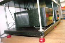
So it looks like the rectifiers are in a tray under the two transformers. Right?
What was your reasoning behind using 25V secondary output transformers and not higher, maybe around 34V?
Where did you buy the Toshiba Mosfets and the Jfets from? I read a post from Tea-Bag mentioning "The FQP variants (FQP19N20C and FQP12P20) are still available via distribution" Did you consider them?
That's a tremendous amount of fantastic machine work you have done!
Thanks nashbap, no machine work just a little Bosch hand drill 😀
Yes, the rectifiers are under the transformers.
The 25 volts give about 32 Volts DC rails which is enough for me, around 100 Watts max. in my 4 Ohm speakers. With my 5 Amp bias around 50 Watts in class A.
No I didn't consider those MOSFETs, I bought the Toshiba MOSFET's rather cheap from NicMac, perfectly matched.
EUVL did also recommend those Toshibas, and I highly respects his work and opinion. Even Pa mentioned the 2SK1530's and 2SJ201's in his F5Turbo article.
JFETs are from Spencer...
Walter
nearly finished time for a redesign
today i finally had the time to start on my aleph 5 mono block's again.
and YESSSS they are allive and kicking😀😀😀
both of them on the first try, no hiss, no hum, no heat.
but alas, i can not measure on the pcb so i have to do a Little redesign so that the pcb can lay on it's back.
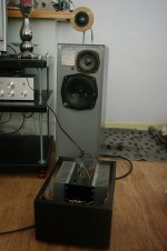
the sound is realy great, even playing unbalanced without a real preamp.
source direct with only a ALPS BB soldered in the interlink.
thank you dear Nelson for your great design. 🙂
today i finally had the time to start on my aleph 5 mono block's again.
and YESSSS they are allive and kicking😀😀😀
both of them on the first try, no hiss, no hum, no heat.
but alas, i can not measure on the pcb so i have to do a Little redesign so that the pcb can lay on it's back.
the sound is realy great, even playing unbalanced without a real preamp.
source direct with only a ALPS BB soldered in the interlink.
thank you dear Nelson for your great design. 🙂
Attachments
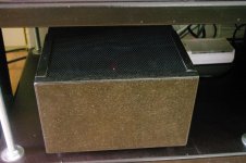
They are heat shrink tube, they hide the melted, pulled back isolation when you are soldering thick wires 😀 I like to work with shrink tube, gives a nice professional look.
I thought soldering will be the best, where high peak currents could be expected...
Walter
Thanks, I also like the HS for neatness and safety, but I had considered some posts for flexibility and ease of use during assembly/adjustments. I like the way you did the insulated faston double pads from the PS. Hadn't seen that before. You really have a showcase build there.
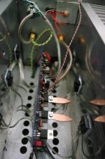
What are grey, yellow, blue and red?
They look like solid core to me.
Usualy those are the standard colours for a transformers secondary windings.
Usualy those are the standard colours for a transformers secondary windings.
Correct that are the two transformers secondary windings, and they are solid.
Nothing you can do about that, it's how Amplimo produces them.
Walter
Solid core are susceptible to fatigue.Change the leadouts to flexible
If you mount the transformer flexibly as you have proposed, then fatigue resistant leadouts will be more reliable.
Change them to flexible leadouts, if you want to flexibly mount your transformer.
While I agree with AndrewT that flexible leads are required when one part can move relative to the other, it does not appear that Walter ended up with any significant flexibility in his build. If I read him correctly, he would have liked to mount the transformer subassembly with flexible mounts, but he did not. I believe the only flexibility in his mount is the standard ~1mm firm elastomer washers that are included with most toroidal power transformers. When the mounting bolt is tightened firmly I suspect that any motion is limited to hundredths of a mm at most. IMHO this will not seriously impact lead reliability.
That said, I have noticed that more expensive toroids tend to have flexible lead outs. Hmm. It might remove a reliability question and it wouldn't be too hard to trim the solid leads fairly close to the transformer and solder flexible leads to the rectifiers. It would also allow another opportunity to use heat shrink tubing. 😉
That said, I have noticed that more expensive toroids tend to have flexible lead outs. Hmm. It might remove a reliability question and it wouldn't be too hard to trim the solid leads fairly close to the transformer and solder flexible leads to the rectifiers. It would also allow another opportunity to use heat shrink tubing. 😉
Last edited:
While I agree with AndrewT that flexible leads are required when one part can move relative to the other, it does not appear that Walter ended up with any significant flexibility in his build. If I read him correctly, he would have liked to mount the transformer subassembly with flexible mounts, but he did not. I believe the only flexibility in his mount is the standard ~1mm firm elastomer washers that are included with most toroidal power transformers. When the mounting bolt is tightened firmly I suspect that any motion is limited to hundredths of a mm at most. IMHO this will not seriously impact lead reliability.
Exactly! And they are tightened firmly!
What I ment with flexible is that I can disassemble the whole amp without having to cut wires from PCB to PCB. So I solved this with the double Faston connectors. I can also take the whole subchassis, with trafos and rectifiers, out of the case. I never intended to get my trafos separate out, or mount only them flexible.
If I would do so it will be the whole subchassis in flexible rubbers.... but I didn't...
Walter
use heat shrink tubing.
 BOBBY
BOBBY You of all folks should know how much vibration several thousands of diesel kW's, at say 2100rpm, can facilitate.
Example of a 60 KW/ton (shaft power/displacement), 45kn top speed screamer from the early '90s.
Structural damage level from excitation forces, led to a few hundred thousand dollars costs in testing & engine room modification.
Plenty of solid copper in those locations, at acceptable vibration levels, easily survive the W6 stretch.
Flexible leads is more of a convenience issue.
Attachments

Last edited:
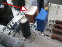
a metal condom??? yeah whell, what the heart is full of right.
but i see copper and on the left side corner i see a cut in the material, that is what got me thinking of a heatsink.
but i see copper and on the left side corner i see a cut in the material, that is what got me thinking of a heatsink.
So, it's a DIY heatsink for a TO92.
Check my pictures on the Pumpy thread for serial manufacture ones (also copper)
Check my pictures on the Pumpy thread for serial manufacture ones (also copper)
Hahaa, it's a DIY heatsink for two TO92's😀
The 2sj74 and the 2sk170 are thermally coupled that way... a bit... best I could do...😉
The 2sj74 and the 2sk170 are thermally coupled that way... a bit... best I could do...😉
You of all folks should know how much vibration several thousands of diesel kW's, at say 2100rpm, can facilitate.
Example of a 60 KW/ton (shaft power/displacement), 45kn top speed screamer from the early '90s.
Structural damage level from excitation forces, led to a few hundred thousand dollars costs in testing & engine room modification.
Plenty of solid copper in those locations, at acceptable vibration levels, easily survive the W6 stretch.
Flexible leads is more of a convenience issue.
Thanks for putting the "problem" in perspective, Jacco. I've been out of that business too long.
Hahaa, it's a DIY heatsink for two TO92's😀
The 2sj74 and the 2sk170 are thermally coupled that way... a bit... best I could do...😉
nice. i don't know when or where, but i remember seeing aluminum blocks for thermal coupling of 2 TO92's. face to face, back to back and face to back, they had them all.
a DIY heatsink for two TO92's)
My mistake, then it's a twin sleeping bag (and a used one on top)
- Home
- Amplifiers
- Pass Labs
- Pictures of your diy Pass amplifier