It helps when the circuitry functions properly. Breadboarding stuff like this can pose problems sometimes, like I've been having here, with bad contacts in the breadboard, that are a bit tricky to find.
Anyway, I dug out a programming seat adapter for pics, so I wouldn't use the breadboarded circuit, at least to eliminate the obvious culprit. Once the pic was removed from the breadboard and put on its own on the zif socketed adapter, with the pickit3 alone, set up to provide power, I was able to erase the memory, reset the pic to be reprogrammed, and the programming was finally successful.
So the whole issue is confined to that breadboard. I went through a bunch of wires, making sure they are seated right, but there is no telling if it'll work right. I'll test this soon. Breadboard are nice, but can also be trouble.
Anyway, after trying out various things, I figured since the triac when fully turned on is given a permanent on via the optocoupler, without any pwm of the gate signal, why not just forgo the pwm all together and just single pulse the trigger with the wide pulse for the whole time it's supposed to be on.
After all, the gate only gets a very short burst of current at the start of the trigger pulse but once the triac is on, the gate current goes down enormously and so there should be no concern about dissipation, at least not in the optocoupler, and the gate resistor.
I'm still not sure about that gate resistor value though. I don't see how this low value could be an issue if commercial amps like the bryston use this as is, and have no issues.
Except for one of their amps where they used a 100ohms gate resistor, all their amps use a 22ohms gate resistor.
And on that amp using the 100ohms, they have that extra funky set up with a relay shorting the gate with a 3ohms. So that's even worse, not 22, but 3ohms, at some point, which I assume might be when the triac must be fully turned on.
Concerning PWM, look at this post using longer pulses, not PWM, it should work with the final HW setup, I had used this way back in 2012 for a leading-edge dimmer, provided you follow the optocoupler circuitry suggested by the datasheet in Fig. 12. One thing I noticed during simulations is that the snubber values of 470R and 100nF helped a lot neglecting the spikes when the TRIAC switched ON. I assume it is possible to tweak these values for the transformer to be used.
Usually, when a lower resistor value is used as for what Bryston did, this implies they are PWM pulsing the TRIAC gate with very small pulses to avoid TRIAC's gate and optocoupler overdrive, I doubt that the duty cycle is 50%, also there is no need to put the optocoupler under stress. Since we want to overcome the PWM pulses (and looking at the fact you are using asm which is tedious already), and use longer pulses to ensure that the TRIAC stays ON, I think this resistor value is inappropriate, measuring the voltage across the 22R resistor will give you an idea whether you are actually exceeding the optocoupler limits or not.
I suggest that you leave the PWM pulsing for now, concentrate on getting the delays correctly, use the longer pulsing method and see what you get, from there you can decide to use PWM or not.
Last edited:
I have to be 100% frank... i have not red the whole thread... but, maybe an FL5150 can be useful here to bypass some issues related with the zc detector and drive of the triac ?
Pulse triggering is used for mainly two reasons.Anyway, after trying out various things, I figured since the triac when fully turned on is given a permanent on via the optocoupler, without any pwm of the gate signal, why not just forgo the pwm all together and just single pulse the trigger with the wide pulse for the whole time it's supposed to be on.
After all, the gate only gets a very short burst of current at the start of the trigger pulse but once the triac is on, the gate current goes down enormously and so there should be no concern about dissipation, at least not in the optocoupler, and the gate resistor.
One is energetic efficiency: some triacs require a largish current to be triggered in some quadrants, and if you can achieve the same result with 100mA^ pulsed at a 1:10 duty cycle as with a continuous 100mA current, it is an attractive option, especially taking into account the difficulty to create an auxiliary gate supply (often a capacitive supply).
The other is that pulses are gate-transformer compatible, unlike DC.
If you have the means to supply the continuous gate current, there is no objection to it
Although the triac's gate current is coming via the optocoupler, the actual gate current comes from the mains and not the supply that powers the led inside the coupler. So the current needs aren't much of an issue there. Isn't that right?
The one thing to consider would be the dissipation, but as mentioned earlier, the gate current handled by the optocoupler doesn't stay high for very long, not enough to cause any dissipation concerns. Not even for the resistor either.
The one thing to consider would be the dissipation, but as mentioned earlier, the gate current handled by the optocoupler doesn't stay high for very long, not enough to cause any dissipation concerns. Not even for the resistor either.
More or less, however you still need to supply enough current to the optocoupler: in the end, it is a (small) triac, and triacs need a frank and massive triggering to remain healthy over time.Although the triac's gate current is coming via the optocoupler, the actual gate current comes from the mains and not the supply that powers the led inside the coupler. So the current needs aren't much of an issue there. Isn't that right?
If you trigger it with just enough current, it will work for weeks, months, sometimes years without apparent problem, and then fail for apparently no reason
Dissipation is certainly not an issue here. The important spec is the Itsm rating (1A for the opto) and the peak gate current allowableThe one thing to consider would be the dissipation, but as mentioned earlier, the gate current handled by the optocoupler doesn't stay high for very long, not enough to cause any dissipation concerns. Not even for the resistor either.
The MOC3052 as used in this circuit has 1A for Itsm but I'm not sure about the triac.
The thing is, the current comes from the mains, and the only thing limiting it is that resistor between the opto and the triac's gate. Not sure exactly how to calculate the actual gate current, but it's not constant anyway, and although some have stated some oddly super high currents due to that low value gate resistor, I doubt this is the case, as it would've blown the triac by now.
I put a 510ohms resistor as the limiter on the led side of the coupler, so we should be getting some ~7.5mA or so of current in that led. Isn't this sufficient?
One thing I do see in the triac's datasheet is a peak gate current of 4A, but it states tp=20us, so I'm not sure what to make of that. We're giving it pulses much longer than 20us, but as mentioned before, the gate current doesn't stay high for very long, as it drops as soon as the triac starts conducting which is somewhat fast. So I see this mostly irrelevant, as we're not getting into that territory..
The one concern that I have is that if instead of pulsing the gate current we give it a whole big long pulse the whole time we need it to conduct, what actual gate current are we really feeding that thing?
You need to account for the worst case: mains at Vpeak, + the tolerance (+10% for example)/Rgate.The MOC3052 as used in this circuit has 1A for Itsm but I'm not sure about the triac.
The thing is, the current comes from the mains, and the only thing limiting it is that resistor between the opto and the triac's gate. Not sure exactly how to calculate the actual gate current, but it's not constant anyway, and although some have stated some oddly super high currents due to that low value gate resistor, I doubt this is the case, as it would've blown the triac by now.
The "super high current" might be present (it also depends on the load and firing strategy), but only for several µs, the time for the main triac to take control.
Note that even if you use 0ohm, the circuit will work.... for an indeterminate period of time.
Short overloads don't cause an immediate meltdown, but a progressive degradation
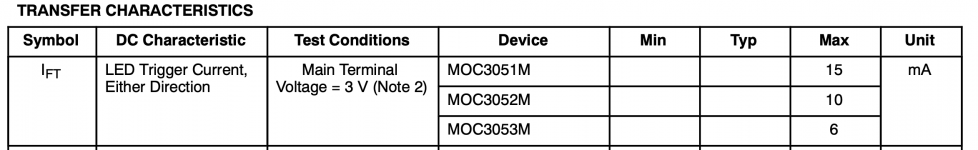
The datasheet max limit is 10mA, thus you should aim for 12mA, to have some marginI put a 510ohms resistor as the limiter on the led side of the coupler, so we should be getting some ~7.5mA or so of current in that led. Isn't this sufficient?
That would be the limiting factor if it was smaller than the 1A Itsm, which is not the case meaning you can ignore it safelyOne thing I do see in the triac's datasheet is a peak gate current of 4A, but it states tp=20us, so I'm not sure what to make of that.
The 12mA is well below the 60mA limit, thus no problem there, and the current in the gate will only exist for the time needed by the triac to trigger and hold.The one concern that I have is that if instead of pulsing the gate current we give it a whole big long pulse the whole time we need it to conduct, what actual gate current are we really feeding that thing?
I cannot think of a situation where a significant A1-A2 voltage is present and the triac fails to trigger.
If the load is inductive and doesn't reach the hold current, the triac will nevertheless conduct like a simple transistor, and divert most of the current away from the opto
Well, I could drop the 510ohms res to maybe a 330 or perhaps even a 316 from the E48 or E96 values. That one doesn't even need to be very big, a 1/4W can suffice.
That would up the led current a bit more, getting somewhere in that vicinity.
That would up the led current a bit more, getting somewhere in that vicinity.
The MOC3052 as used in this circuit has 1A for Itsm but I'm not sure about the triac.
The thing is, the current comes from the mains, and the only thing limiting it is that resistor between the opto and the triac's gate. Not sure exactly how to calculate the actual gate current
ITSM is the peak current allowed through the MOC3052. So the resistor is simply the peak voltage divided by 1 A. On 230 V, allowing for ±10 % mains variation, that comes to: R = (230*1.1*sqrt(2))/1 = 358 Ω. 360 Ω is an E-24 standard value. 390 Ω would be the nearest higher E-12 value.
I doubt this is the case, as it would've blown the triac by now.
Not necessarily. The limit specified in the data sheet is usually the value that will ensure operation for "a lifetime" (typically 10 years).
I put a 510ohms resistor as the limiter on the led side of the coupler, so we should be getting some ~7.5mA or so of current in that led. Isn't this sufficient?
Probably. You could consult the data sheet. Attached screen shot is from ON Semiconductor's MOC3052 data sheet.
One thing I do see in the triac's datasheet is a peak gate current of 4A, but it states tp=20us, so I'm not sure what to make of that.
It means it can handle a 4 A pulse of 20 µs duration. You may be able to find a figure in the data sheet that shows the max gate current as function of pulse width.
The gate driver can only handle 1 A, so that's the limiting factor.
The one concern that I have is that if instead of pulsing the gate current we give it a whole big long pulse the whole time we need it to conduct, what actual gate current are we really feeding that thing?
You mention pulse-width modulation. I think you may be misunderstanding how TRIACs work. They turn on when the gate current exceeds the minimum trigger current. They remain on until the current through them falls to zero. Depending on the reactance of your load, this may/may not be at the zero crossing of the mains voltage.
If you want to be able to turn the current on/off at will, you'll need to use something like a MOSFET transmission gate.
Tom
Attachments
This is quite some engineering for such a simple task isn't it? I am sure there are audio circuits out there that had less development time. Still I am curious what the benefits are compared to old fashioned ways of soft starting.
May I suggest to add a DC blocker for toroids? As can be read in various threads the hum issue is common with many toroids and it can be implemented on the board. It would be a pity that the circuit works wonders but then the toroid is humming.... mains pollution is a challenge with LED lighting and SMPS in many homes, just as a mains filter meanwhile is a necessity. The remarks are constructively meant just to avoid a 3 PCB end situation with too much wiring of the dangerous kind...
May I suggest to add a DC blocker for toroids? As can be read in various threads the hum issue is common with many toroids and it can be implemented on the board. It would be a pity that the circuit works wonders but then the toroid is humming.... mains pollution is a challenge with LED lighting and SMPS in many homes, just as a mains filter meanwhile is a necessity. The remarks are constructively meant just to avoid a 3 PCB end situation with too much wiring of the dangerous kind...
Last edited:
See first page. 🙂
Although a few odds and ends should be added to it for a more full blown build, like a dc blocker at least, to limit the toroid hum...
Ah Ok, separate board then. In my experience the least mains wiring the tidier en ... safer. I think I would even use a solder version of the IEC inlet with built in fuse and mains filter.
Personally I hate unnecessary wiring and always try to avoid any whenever possible.
This little project was aimed at those who take bits and pieces here and there, and wire it all up with a big sack of wires ;-)
I will make a version with a dc blocker on it, as I had mentioned before.
I also prefer using some kind of inlet module, so the mains plugs right into it, and it can have the filter, fuse, and for some even a switch sometimes..
I designed a much more all-in-one board, with dual PSUs for power amps, dc blocker and a ground lifter for each side, and the soft start does both toroids in sequence. Plus it has an inlet module, so the wiring is way down on that one. Much tidier. The only wires are from the toroids to the main board, then each power amp gets its set of wires from the separate PSUs. So minimum wiring there. Not bad with a single pcb.
There is one thing I've been pondering about: I would think the triac needs a gate current somewhat proportional to the load current it needs to handle, so if the gate current isn't "forceful" enough, then wouldn't that be some potential for misfiring under full load?
An all-in-one-board... Yoda is here for a visit and he says: "may the Force be with you".
Please let those people have as least wiring as possible is the lesson one learns after some projects. Safely executed mains wiring with crimping tools is then done eh.. without crimping tools. Wires with mains voltage soldered to PCB's ... Recently I got to see a project of someone that wired mains voltage without fuses or switch ... I am convinced that in DIY more do it wrong then right so it should be as complete and safe as possible without added risk. The concept of PE is unknown by many (really!). The elite of DIYers, the tube crowd, very often connect audio GND to the casing instead of PE....
This little project was aimed at those who take bits and pieces here and there, and wire it all up with a big sack of wires ;-)
Please let those people have as least wiring as possible is the lesson one learns after some projects. Safely executed mains wiring with crimping tools is then done eh.. without crimping tools. Wires with mains voltage soldered to PCB's ... Recently I got to see a project of someone that wired mains voltage without fuses or switch ... I am convinced that in DIY more do it wrong then right so it should be as complete and safe as possible without added risk. The concept of PE is unknown by many (really!). The elite of DIYers, the tube crowd, very often connect audio GND to the casing instead of PE....
Last edited:
I'm making a version with a TOP3 Triac and a dc blocker.
I won't use a bridge to have 2 diodes drops in series, but instead only single diodes and have only one drop. Plus using schottky rectifiers also lowers that drop some.
This will allow blocking dc components of low voltage, as even 1V or so of dc could bother some toroids.
I picked the SR1503 schottky rectifier, which is pretty beefy with a 15A direct current and its voltage drop is supposed to be .55V only. So any dc above that will be blocked, which should somewhat please the toroids a bit better.
I'll be looking for possible supercaps, if some can be used..
Well if it makes you happy overengineering everything then do so 🙂
What is the maximum current in a home in your country? There are reasons the standard DC blockers are made like they are. Make sure the supercaps and boards are mounted mechanically sturdy as these caps may contain a lot of energy and the risk of explosion is a real one... Anyone should do what is best but I really think supercaps are not the optimal choice for mains related circuits.
What is the maximum current in a home in your country? There are reasons the standard DC blockers are made like they are. Make sure the supercaps and boards are mounted mechanically sturdy as these caps may contain a lot of energy and the risk of explosion is a real one... Anyone should do what is best but I really think supercaps are not the optimal choice for mains related circuits.
Last edited:
About a dc blocker, I'm pondering the use of supercaps, which have very low voltage handling, but that would be fine for a dc blocker. Even a 2.5V cap can be used for a dc blocker, so the supercap voltages shouldn't be a problem.
And with their small size for their large capacities, it's pretty good to save pcb real estate.
The one thing I wonder about using such things is how well they would handle large currents.
The surge currents would be handled by the diodes, when there is any, so that's not where they have to perform.
Since having a few surprises I always count on things that may go wrong and what will happen if so. If I had to use supercaps for a toroid DC blocker I would choose an R-core transformer as usual and no DC blocker. Way simpler.
I suspect most european countries use basically the same system and similar plugs.
The most common grounded plug circuits here are 16A and in some cases we can find 20A circuits, although no guaranteed to be there when you're roaming with some gear. So, better bet on just a 16A circuit. Sill, with usually some 230-240V, that's more than enough power for most audio gear.
The most common grounded plug circuits here are 16A and in some cases we can find 20A circuits, although no guaranteed to be there when you're roaming with some gear. So, better bet on just a 16A circuit. Sill, with usually some 230-240V, that's more than enough power for most audio gear.
- Home
- Amplifiers
- Power Supplies
- PIC based stand alone soft start