If a diode fails short, then not too much really happens. The dc passes, so the blocker no longer works. But the cap isn't affected, as it's "protected" by a short across it.
So in case of one of the diodes failing short, all that happens is the dc blocker no longer blocks dc, that's all. The toroid will complain if dc is present, which hopefully will prompt the "tech" to investigate and root out the culprit.
So in case of one of the diodes failing short, all that happens is the dc blocker no longer blocks dc, that's all. The toroid will complain if dc is present, which hopefully will prompt the "tech" to investigate and root out the culprit.
It can happen. Things can go wrong in various ways. I have spent some time investigating incidents and defects. I count on every part to possibly fail and what may occur if it happens. Had too many thyristors, IGBTs and other parts blown to pieces without no apparent cause (at first).
Last edited:
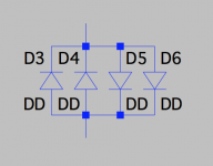
To illustrate, if a bridge is used this way, with the + & - shorted, as it's usually done, and also both ~ ends shorted as well, we get 2+2 diodes worth..
Only a single drop instead of 2, and double the current capacity.
Requires a larger cap though, to keep things proper, but still very low voltage.
Only a single drop instead of 2, and double the current capacity.
Requires a larger cap though, to keep things proper, but still very low voltage.
Attachments
"if" a diode does fail open, and high voltage types were used, like 400V or whatever, sure the other diodes may not croak over the high voltage coming all of a sudden, but the cap still would blow! So what's the real advantage there? Not very much.. Still damage.
I already wrote that to be true as Mark Johnson pointed that out. If one of the parts fails the other likely fail too. Just like I wrote that the idea of paralleling diodes to have higher current ratings is a bad idea and that a tiny load may present a nice high current short so parts should be dimensioned accordingly. But if you like confirmation I can repeat that if the diode shorts not much happens and if it becomes open circuit the whole circuit will end up in smoke anyway. So now a reaction to my points.
It is NOT usually done like that. They are normally used in anti parallel config in series with another set of anti parallel diodes.
To illustrate, if a bridge is used this way, with the + & - shorted, as it's usually done, and also both ~ ends shorted as well, we get 2+2 diodes worth..
It is NOT usually done like that. They are normally used in anti parallel config in series with another set of anti parallel diodes.
Last edited:
I had a lot of fun trolling an undereducated sourpuss curmudgeon here on diyAudio who was afflicted with the "Often wrong but never in doubt" disease.
I posted the schematic below including the "red resistor" and then commented that some people recommend Rred = infinity while others (including Rod Elliott and Bryston Amplifiers) recommend Rred = 0 (short circuit).
Then I listed three or four different equations which gave different numerical results for the optimum value of Rred. It wasn't zero and it wasn't infinity.
Our curmudgeon had a quintuple fecal haemorrhage right here on diyAudio, because these equations and their resulting resistance numbers did not match ANY of the patterns he had previously memorized, and he was more comfortable operating from "pattern matching" rather than deep understanding and fundamental knowledge. When I asked him to point out the error(s) in the equations he just got more and more obstinate and belligerent, but was unable to explain why some Rred values were acceptable and others were not.
It was a lot of fun, but moreso for one of the two of us, than the other.
_
Attachments
If all four diodes were equal (identical device characteristic, same temperature, same current, etc.) the current through Rred would be zero. In reality the diodes won't be identical - even if they're all part of the same diode bridge - so some current will flow in Rred.
It wouldn't surprise me if you could find an optimal value for Rred that would compensate for the imbalance in the bridge. I would be surprised it the difference was large, though.
I'd be interested in hearing a little more about how much benefit you observed from tuning Rred.
Tom
It wouldn't surprise me if you could find an optimal value for Rred that would compensate for the imbalance in the bridge. I would be surprised it the difference was large, though.
I'd be interested in hearing a little more about how much benefit you observed from tuning Rred.
Tom
read (article index)
Sjostrom Audio - DCT03 The DC trap, high-end style heavy duty
btw: Per-Ander's method contradicts some things mentioned here lately.
If it's a bad idea to have more than one diode in parallel, then what he's doing isn't quite right, with 4 strings of them in parallel. Was he wrong to do it that way?
And then he's putting 4 diodes in series in each string, so depending on their drop, we're talking about something in the order of about 4V across them, so that is that much DC that can still pass. If a grouchy toroids see that much DC, he's surely going to let us know..
I think there is gross misinterpretation of reality here.
The dc removed by the blocker isn't "below" a certain range, but "above" it.
It will let some dc pass, when it's "below" the the diodes' drop.
If it was removing in that range of 0 to whatever, then what would happen to larger dc then?
What if some 10 or 15V of dc shows up there??? That doesn't jive.
With such large dc coming in, the dc blocker should remove most of it, and if the dc is "lower" than what the blocker can remove, then that just gets through. Which is also why I think it would be better if the threshold was lower, so as little as possible of the dc makes it to the toroid, so keep it happy and make it shut up.
Too many various "opinions" with differing interpretations and not enough demonstrations as to what really does happen.
As far as I can see it, with this use of big bridges being so common, it's just due to the convenience and low cost of those bridges, that can afford some very sturdy rectifiers in a convenient all-in-one package, which provides high current carrying capabilities and likely don't even require any extra heatsinking.
But I see nothing wrong with doing this with only one diode drop, if a sturdy enough diode can be obtained, and if it's a schottky, even better, with a lower drop, which also lowers the dc removal threshold.
You are wrong !
What do you put in front of amplifier input to remove DC ? Capacitor or diodes ?
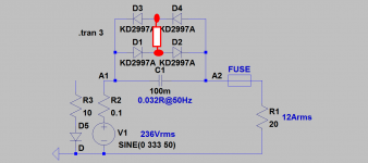
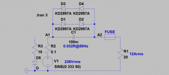
Simulation run 30 sec
NO DC component, SINE(0 333 50)
Fourier components of V(a1)
DC component:0.0297197
Fourier components of V(a2)
DC component:0.0103036
Then I add "normal" DC +10V, SINE(10 333 50)
Fourier components of V(a1)
DC component:10.4661
Fourier components of V(a2)
DC component:9.68967
What do you put in front of amplifier input to remove DC ? Capacitor or diodes ?
Simulation run 30 sec
NO DC component, SINE(0 333 50)
Fourier components of V(a1)
DC component:0.0297197
Fourier components of V(a2)
DC component:0.0103036
Then I add "normal" DC +10V, SINE(10 333 50)
Fourier components of V(a1)
DC component:10.4661
Fourier components of V(a2)
DC component:9.68967
Attachments
What am I wrong about?
Anyway, this doesn't make much sense. If this is how it goes, it's backwards and not very useful. If let's say something like 400mV of dc shows up, then that would be removed, but then 10V shows up and only a small part of that gets removed and the rest goes through unimpeded. Not good.
And while at it, comparing all those various ways it's been done, here is one more, where there is nothing between the 2 diode strings (earlier referred to as Rred):
https://scintilla-buizenversterkers...bouw/zelfbouw sites/DC-Blocker/DC Blocker.GIF
And then there is one old implementation from crown that had no cap at all, just 2 bridges. Now how would that stop any dc? Beats me!
I completely agreeIf one of the diodes fails and becomes an open circuit, then the capacitor is unprotected in one direction, and the capacitor will explode.
Besides, how does a diode usually fail? Rarely anything other than a short.. So high voltage isn't what happens then, but rather nearly nothing. And it still fails regardless.
As a rule, semi's rarely fail open; there are some exceptions though: if the current is high enough, some parts of the diode may act as a fuse, especially the bonding wire if present. For that reason, epoxy encapsulated diodes are more reliable than metal types, because the bonding wire surrounded by the molding compound doesn't melt as easily, but even better is the metallurgical bond where there is no wire at all.How often does a diode fail open rather than a short?
Epoxy-encapsulated devices can suffer from other problems: the thermally-induced stress can make the bonding fail open, thus metallurgical types are the best option (never 100.000% safe though)
In general, for current-sharing yes, but here the supplementary device acts as a safety net for the first one: if it happens to fail, the second one will prevent an open circuit.The paralleling of diodes for higher current rating is a bad idea.
If the current is sufficient to vaporize the first diode, it could also do the same with the second, but in fact this is not true: under gross overload conditions, the Vbe mismatches completely vanish and Vf is determined solely by the purely ohmic resistances which normally match rather well between identical devices, meaning the effective surge current will be ~doubled.
Of course, doubling the diodes will also square the natural failure rate of a single diode: if the the failure rate is 0.1% under certain conditions for one diode, it will fall to 1ppm for two diodes, thus it is beneficial
The opposite is true: as long as the DC is below the threshold voltage, it will be eliminated (assuming a simple diode model).I think there is gross misinterpretation of reality here.
The dc removed by the blocker isn't "below" a certain range, but "above" it.
It will let some dc pass, when it's "below" the the diodes' drop.
If it was removing in that range of 0 to whatever, then what would happen to larger dc then?
Note that if the capacitor is not large enough, the DC threshold will be "blurred" (and thus reduced) by the AC amplitude, reducing the effectiveness of the blocker
So, basically, any "large(ish)" dc WILL make it through regardless, so this isn't effective enough in all cases.
now asymmetric load, dc in ac
R3=10ohm
Fourier components of V(a1)
DC component:-0.624333
Fourier components of V(a2)
DC component:-0.120614
R3=3ohm
Fourier components of V(a1)
DC component:-2.85073
Fourier components of V(a2)
DC component:-2.18409
Put 4 diodes in series and large cap (low imp) then can help.
or use big cap for mains voltage and no diodes at all ��
Last edited:
- Home
- Amplifiers
- Power Supplies
- PIC based stand alone soft start