That's not what I said. I wasn't referring to this particular setup with those values.
I was only referring to what many have been calculating for, thinking it MUST be done that way, but I just don't see the valid reason behind it.
Let's take a 2kVA toroid, which would draw something like 8.5A at full load (rms). Why would it have to be done so all of that flows only through the caps and not through the diodes, and only fault currents would ever pass through the diodes???
I see nothing wrong with having at least some of the normal current going through the diodes, which at the same time puts a limit to how much goes through the caps, which limits their stress.
100mF is the value I had calculated earlier, aiming for supercaps use, if that could be done, and making sure all the normal current would flow through the caps and only anything beyond would go through the diodes.
But that's not necessarily the goal to reach. There is no need to make sure that ALL of the normal current goes through only the caps. The diodes can also pass some of it in normal condition. There is no good reason that I can see against that.
The real goal is to remove as much as possible of the DC from the mains, to keep the toroids happy and silent.
And that is why I was looking at only one diode's drop and not 2 to introduce, and even make use of schottky to reduce that drop.
And the fuse shouldn't go after all this. It should be place ahead of it.
I've been doing sims like this too. Trying various values, but I'm putting only one diode, not 2 in series.
And I didn't insert any R2 res in the mains. I don't think the mains impedance plays that much of a role there anyway.
The fuse should be the very first thing in line for sure.
I've been doing sims like this too. Trying various values, but I'm putting only one diode, not 2 in series.
And I didn't insert any R2 res in the mains. I don't think the mains impedance plays that much of a role there anyway.
The fuse should be the very first thing in line for sure.
imho, diodes should be for 400VDC
fuse is for illustration, not the exact position
you don't understand me, sorry
fuse is for illustration, not the exact position
you don't understand me, sorry
Last edited:
For diodes, since they are in reverse parallel, they never ever "see" anything beyond their drops, both ways, so not only the cap is never exposed to anything harmful, the diodes also never see any significant voltage, so thinking about the mains voltage and trying to size them up for that, with extra margin, looks pointless.
And I'm also referring to the current passing through them which does need to be taken into account, while the voltage isn't an issue for them.
And I'm also referring to the current passing through them which does need to be taken into account, while the voltage isn't an issue for them.
And one more thing, about the limits of mains circuits, which are pretty much set by the breakers or fuses: the actual limits to look at aren't the mains circuit's but rather the device or unit which should have its own built-in breaker or fuse, which should be chosen according the the unit and not the mains circuit's limits.
In case of fault, the mains circuit's breaker or fuse doesn't have to be tripping or blowing, as it's the one in the unit that should go first, as the caliber should be set right for the unit and should be well below the limits of the mains circuit.
This is wrong, sorry. Any course on breakers and/or energy distribution will teach otherwise. See the load as a black box that can consume from 0 Ampere to possibly infinite Amperes for a very short time (i.e. a short circuit). Then calculate with the nets impedance and breakers reaction time etc. how large the possible surge/short circuit current can be despite the breaker being a B type 16A. The mechanical power that can occur can destroy automatic breakers if they were not chosen carefully.
Of course the devices fuse wil have to be chosen according the ratings of the device and for selectivity but it is mainly protection of the home wiring/installation, to reduce risk on fire etc. and only then the device itself. The idea of having in fact 2 fuses or a breaker and a fuse is that when one would not break the current the next one will. All is about protection of the installation, safety and not the interest of the defective device.
The device can consume just 1A but when something goes wrong with any of the parts it can be a short circuit and then the net + breaker define what possible short circuit current can be produced for a certain amount of time (and not the device that consumed just 1A). That is why sane engineering uses parts that can withstand the possible currents.
Last edited:
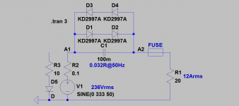
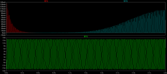
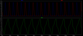
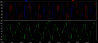
LKA, can you please show simulation for 30mF? For both normal operation and one half of sine wave loaded by 10R to create DC.
Thank you in advance.
Thank you in advance.
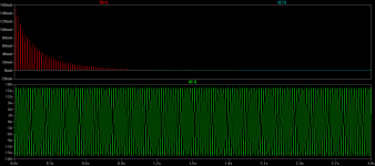
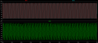
C1=30mF (imp 0.1R at 50Hz), in both cases traces look similar
12Arms is cc 16.5Apeak, the voltage drop across a cap is 16.5*0.1=1.56Vpeak, greater than two diode drops 2*0.6V=1.2V, so diodes will conduct for some preriod
of course, 30mF is good value when less current flows
- capacitor filters the dc, not diodes
- diodes protect the capacitor, handles transients and a portion of a flowing current when voltage drop across the capacitor exceeds diodes forward voltage
- capacitor should be high-current type
- diodes should have 35A/400V rating
Attachments
Thank you for the sims 🙂
High current type, how to recognize it is?
I think 30mF is perfect for 0.4~1KVA.
High current type, how to recognize it is?
I think 30mF is perfect for 0.4~1KVA.
and this is my soft start pcb, rear panel mounted components (iec inlet, fuse, switch) are not shown on the schematic
Ka1 - AC Power Controller - Google Photos
Ka1 - AC Power Controller - Google Photos
diodes should have 35A/400V rating
35A / 20V rating is perfectly adequate since the none of the diodes is ever reverse biased by 3 volts, never mind 400 volts.
D3+D4 protect D1+D2 from reverse bias.
D1+D2 protect D3+D4 from reverse bias.
_
So if one of the diodes would fail that protection is lost. So it does make sense to choose 400V diodes as usually chosen 🙂 There is also no sound reason to choose 20V diodes in mains voltage circuits when 400V diodes are standard. Reality versus simulation.
Last edited:
That was my point earlier already.
They are mutually clamping the voltage, at all times, even when currents are very high, although the drop will climb with the high currents, it will never be more than a few volts at the very worst. No need for any high voltage diodes at all. Only good current carrying types.
And I was experimenting (sim) with the usage of a bridge that would have not just the + and - shorted to put the diodes in antiparallel, but also both ~ sides could be shorted as well, putting all 4 diodes in the bridge in parallel, 2 by 2 in antiparallel. Doubling the current capacity while cutting in half the total drop.
The dc being removed is not "up to xV"... It's more "from xV and up"...
So the lower the drop on the diodes, the better to remove as much dc as possible. Lower dc will make a toroid happier.
If one of the diodes does fail, other things will quickly follow anyway. When you get to that point, much of it will go up in smoke anyway.
If one of the diodes fails and becomes an open circuit, then the capacitor is unprotected in one direction, and the capacitor will explode.
Either you need all four diodes, or you don't. If you need them, then when one goes open circuit the circuit fails. If you don't need one or more of them, take them out.
Either you need all four diodes, or you don't. If you need them, then when one goes open circuit the circuit fails. If you don't need one or more of them, take them out.
- Home
- Amplifiers
- Power Supplies
- PIC based stand alone soft start