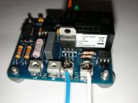
I built a prototype on pcb as planned, the version as posted at the top of this thread.
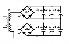
I use a makeshift load as shown, with a 200va toroid, 2 bridges and 6 10mF caps. Plus to add a bit of load to that psu, I put light bulbs on each side.
Although not a big load, this is very similar to actual real world psu used in power amps.
It'll be more reliable than breadboarding, and I'll try out some software ideas.
I don't have a lit push button, so I didn't mount the header and just put a led there, with wires to simulate a push button switch.
I used an old optocoupler that I have on hand, SL5501, which should work about the same as the CNY17 type.
This version is only for TO220 triacs, and there is no heatsink, so not aimed at huge toroids. Although a small heatsink could be added to the triac..
Attachments
Ok, here is the rest of it.
I had to zip up the source code file and the excel BOM.
The gerbers are those I used lately to order the pcbs, which are already made and shipped out to me. I'm awaiting reception in a few days. And I will build and test it again.
The source code is PIC assembly, not C or whatever... Done with MPLabX, and I used a pickit3 to program my chips to test on breadboard.
Others have done similar builds (hello Nigel 🙂🙂🙂).
I'm a first timer at PICs, and it's, almost, my first PIC assembly program, as I already did one before this one that was aimed at 2 toroids plus a few other features.. I also did one other program to do housekeeping for a headamp.
As a first timer, I heavily document my asm source code, so I can go back much later and know more or less what I did without doing too much head scratching. This should also be good for other noobs like me to learn some more and get into it.
It was a nice exercise, but it should be useful.
It may be worth checking the startup characteristics, the 12PICF series as the timer oscillator takes 1024 cycles before it stabilises, then it starts your initialisation routine. I assume that the triac is off before the PIC starts?
The PIC will be high impedance outputs until the code configures it.
The opto-coupler shouldnt turn on in that state.
I have been programming PIC's since 1985 and still find the PIC12f508 useful for small projects. Easy to use and cheap.
The opto-coupler shouldnt turn on in that state.
I have been programming PIC's since 1985 and still find the PIC12f508 useful for small projects. Easy to use and cheap.
The PIC will be high impedance outputs until the code configures it.
The opto-coupler shouldnt turn on in that state.
I have been programming PIC's since 1985 and still find the PIC12f508 useful for small projects. Easy to use and cheap.
Cool. That's good to know. I've done my fair share of 6502, ARM, 68000 and BlackFin assembler. I couldn't see anything that sprang out in the 12PIC manual.
It may be worth checking the startup characteristics, the 12PICF series as the timer oscillator takes 1024 cycles before it stabilises, then it starts your initialisation routine. I assume that the triac is off before the PIC starts?
That's quite interesting and may require some investigating to make sure.
However I had provided for some extra delay for settling time, so I will double check but what I did may be sufficient time for all that to be ready.
And yes, the triac is off by default by software at initialization.
Cool. That's good to know. I've done my fair share of 6502, ARM, 68000 and BlackFin assembler. I couldn't see anything that sprang out in the 12PIC manual.
I've done quite a bit of assembler as well, but not for the ARM. I did a lot of 6502, Z80, x86 and some 68000. Long ago.
And I never got to learn any flavor of C and I'm not about to do so. That means assembler is all I want to do. So now I'm adding the PIC to my list..
And yes, the triac is off by default by software at initialization.
I was thinking of the period from power on to the point of initialisation by software however Nigel answered that 🙂
I was thinking of the period from power on to the point of initialisation by software however Nigel answered that 🙂
I see. Well then, that plus the software afterwards, should make this ok.
I actually tested what I wrote and it performed just fine. However I'm exploring further the way to trigger the triac. I was only giving it a 250u pulse and let it "stick" on its own until the end of the half wave. Now I'm looking at a train of pulses instead of just one.
The thing is, I came across some issue that I have yet to resolve. For some reason I don't yet understand, the zcd sometimes misses a half wave, or more. I've tried various things, like giving more current to the optocoupler, trying both with and without interrupts, and it does the same thing. I use the interrupt on change and it sometimes doesn't "see" some changes. Dunno why.
You could combine cpld (pwm & triggering), with a pic - and add for current sensing. As long as the pic can sample and update the duty rate the cpld would handle the pwm timing.
I’ve done current chopper control for servos, so as long as the sense-control cycle rate can react fast enough.
8bit adc could give, for a 1A current could give a few mA granularity but temperature stability may affect accurancy.
I’ve done current chopper control for servos, so as long as the sense-control cycle rate can react fast enough.
8bit adc could give, for a 1A current could give a few mA granularity but temperature stability may affect accurancy.
Last edited:
- Home
- Amplifiers
- Power Supplies
- PIC based stand alone soft start