Jaap,
But as far as I understand the Garter Bias circuit, your schematic of post # 10538 does not use the Garter Bias method.
That's my sense too, but I'm thinking I'm just not understanding what Jaap has done. Looking for some understanding here. I'd love to know how that schematic works as garter bias.
Edit: To clarify my confusion, garter cross-references the DC bias keeping the tubes in PP running reasonably balanced. I just don't see how that circuit has DC cross-referencing. There is no reference that I can see between the grid of one tube and the cathode of the other.
Last edited:
Jaap's individual "current sink biasing" allows individual biasing of DC current in each output tube.
And then, All AC (signal currents) in the cathode circuit are joined by the two electrolytic capacitors. So, the cathodes move together for all signal voltage variations.
In the Class A operation, the cathode voltages varies very little or not at all.
The resistor to ground at the junction of the two electrolytic capacitors keeps the DC voltage at each capacitor's + terminals to always be positive, and never to go negative.
That circuit is effective, and well proven.
You can also use self bias resistors, instead of current sinks, if you do not have a current sink, or you prefer simplicity.
Last edited:
I still don't see it. There's no cross-referencing between the tubes that I can see* (but I DO want to understand if I'm wrong). Yes, it may well balance DC bias (the CCS could do that) but the way I understand garter bias is specifically the cross-referencing. Current in one tube directly adjusts the current in the other to keep them balanced. That's the piece I still don't see in Jaap's schematic. Whether or not true garter bias is good is a separate question of course...
* at least WRT DC bias
* at least WRT DC bias
Personally I dont't mind how the construction is called. One advantage seems to be that you don't have to match the output tubes. I simply found the design somewhere at this forum. I don't remember where/
See also: Triode PP OP stage combining Blumlein Garter and CCS bias - anyone tried this?
See also: Triode PP OP stage combining Blumlein Garter and CCS bias - anyone tried this?
Thanks 6A3.
Jaap, it's not a problem. I was just confused by the use of the term garter bias when I couldn't see it. I don't have a ton of confidence in my grasp of schematics but I was pretty sure it wasn't. Hence my questions.
Cheers and thanks.
Jaap, it's not a problem. I was just confused by the use of the term garter bias when I couldn't see it. I don't have a ton of confidence in my grasp of schematics but I was pretty sure it wasn't. Hence my questions.
Cheers and thanks.
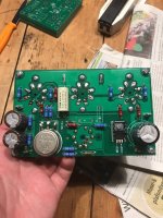
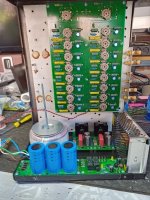
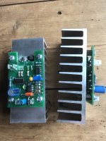
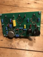
Photo dump, no amps just PCB's
Heres some Photo's from this years FR4 harvest.
No context just epoxy resin fibeglass.
Heres some Photo's from this years FR4 harvest.
No context just epoxy resin fibeglass.
Attachments
-
 2x6080reg1.jpg146.8 KB · Views: 561
 -
 MIC5156 LDO 6.3VDC supplies.jpg144.6 KB · Views: 258
 -
 24V PL36 REG2.jpg136.7 KB · Views: 238
 -
 24V PL36 reg1.jpg158.6 KB · Views: 270
 -
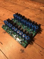
 16X EL84 on one PCB two channel single ended.jpg152.8 KB · Views: 352
 -
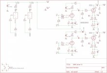 6B4G Driver schematic.jpg508.5 KB · Views: 303
 -
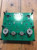
 6B4G driver underside.jpg130.8 KB · Views: 539
 -
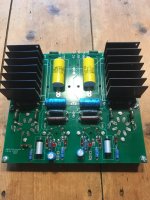
 6B4G driver topside.jpg124.2 KB · Views: 531
 -
 5A DHT REG2.jpg125.3 KB · Views: 539
 -
 2x6080reg2.jpg126.7 KB · Views: 555
Jaap,
I was not criticizing.
I do try and correct in-proper naming of circuits when I can.
You correctly stated, the 2 currents sources means you do not have to match the tubes
(actually current sinks in this case).
They will have current according to the current sink settings, so the cathode currents can be made equal.
But there is more to that story.
That works great for Triodes, the current in the primary halves will be equal, preventing early saturation of the laminations. But if the transconductance of the Triodes are un-equal, there will be 2nd harmonic distortion.
That is a good reason to use matched triodes.
For Pentodes and Beam Power tubes, in their “native” modes, equal cathode current only means equal ‘screen + plate current’. But one tube may have more plate current than the other plate (one tube might have 3mA screen and 37mA plate, and the other tube might have 7mA screen and 33mA plate).
Again, if the two tube transconductances are not equal, there will be 2nd harmonic distortion.
That is a good reason to use matched tubes.
For Ultra Linear operation, the effective magnetic fields are ‘screen 1 current times UL turns’ + plate 1 current times plate turns’; versus ‘screen 2 current times UL turns + plate 2 current times plate turns’.
Again, we need transconductance matching, or we get 2nd harmonic distortion.
That is a good reason to use matched tubes.
The saturation, or early saturation comes from un-matched primary currents.
The 2nd harmonic distortion comes from non-cancellation due to un-equal transconductance.
We can use global negative feed back to reduce the 2nd harmonic distortion.
But global negative feed back can not reduce or fix the saturation.
Make the amplifier perform as well as possible, before applying global negative feedback.
Thanks for you reaction
I have no problem at all with criticism or something that looks like it !!
Good to learn something, so thank you for your comments.
I have no problem at all with criticism or something that looks like it !!
Good to learn something, so thank you for your comments.
Jaap,
I was not criticizing.
I do try and correct in-proper naming of circuits when I can.
You correctly stated, the 2 currents sources means you do not have to match the tubes
(actually current sinks in this case).
They will have current according to the current sink settings, so the cathode currents can be made equal.
But there is more to that story.
That works great for Triodes, the current in the primary halves will be equal, preventing early saturation of the laminations. But if the transconductance of the Triodes are un-equal, there will be 2nd harmonic distortion.
That is a good reason to use matched triodes.
For Pentodes and Beam Power tubes, in their “native” modes, equal cathode current only means equal ‘screen + plate current’. But one tube may have more plate current than the other plate (one tube might have 3mA screen and 37mA plate, and the other tube might have 7mA screen and 33mA plate).
Again, if the two tube transconductances are not equal, there will be 2nd harmonic distortion.
That is a good reason to use matched tubes.
For Ultra Linear operation, the effective magnetic fields are ‘screen 1 current times UL turns’ + plate 1 current times plate turns’; versus ‘screen 2 current times UL turns + plate 2 current times plate turns’.
Again, we need transconductance matching, or we get 2nd harmonic distortion.
That is a good reason to use matched tubes.
The saturation, or early saturation comes from un-matched primary currents.
The 2nd harmonic distortion comes from non-cancellation due to un-equal transconductance.
We can use global negative feed back to reduce the 2nd harmonic distortion.
But global negative feed back can not reduce or fix the saturation.
Make the amplifier perform as well as possible, before applying global negative feedback.

- Home
- Amplifiers
- Tubes / Valves
- Photo Gallery