Been on a VR tube kick. Added a 0A2, a 0B2, and a MOSFET to regulate the screens of the 6T9 spud amp. Please refer to the title.😀
The way you have extended the lead length on the central resistor, looks very neat, can you explain what you did here?
looks tidy 🙂
The way you have extended the lead length on the central resistor, looks very neat, can you explain what you did here?
looks tidy 🙂
Link here.

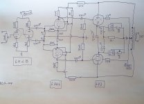
I took the liberty
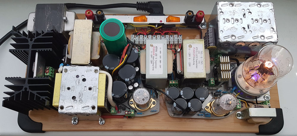
to make some changes to this RCA design. I used the sub-miniature 6N16B at the front end (katode resistor 4K7) en put the mosfet ripple filter of the engineers amp (Pete Millett) in it for the 6AU6 and 6V6. The 6N16 is fed by a mosfet regulator (T-Reg -Jan Didden). A 555 unit is coupled to a Sharp Solid State Relais to get a delay for the PSU. I used some 60 year old old (high quality) Dutch Unitran OPT's (9U13). I changed the coupling capacitors to 0,33 uF after the phase splitter, and took Ero KP1832 0,52 uF's for the 6V6 tubes. This because I had those in the inventory. I must say that this amp sounds glorious, although I suspect it will win no beauty contest. Although the Blumlein Garter bias under the 6V6 tubes is very attractive.
to make some changes to this RCA design. I used the sub-miniature 6N16B at the front end (katode resistor 4K7) en put the mosfet ripple filter of the engineers amp (Pete Millett) in it for the 6AU6 and 6V6. The 6N16 is fed by a mosfet regulator (T-Reg -Jan Didden). A 555 unit is coupled to a Sharp Solid State Relais to get a delay for the PSU. I used some 60 year old old (high quality) Dutch Unitran OPT's (9U13). I changed the coupling capacitors to 0,33 uF after the phase splitter, and took Ero KP1832 0,52 uF's for the 6V6 tubes. This because I had those in the inventory. I must say that this amp sounds glorious, although I suspect it will win no beauty contest. Although the Blumlein Garter bias under the 6V6 tubes is very attractive.
Attachments
Last edited:
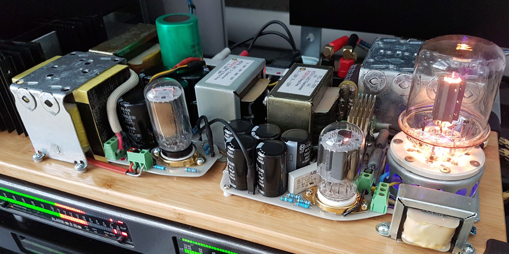
Rebuilt the 6V6 amp. 6EJ7 triode strapped. 6V6 running in beam tetrode mode with regulated screen supply (0A2, 0B2, MOSFET source follower). 9% plate to grid feedback and 8dB GNFB. In lieu of an indicator light, I stuffed a pair of blue LEDs in antiparallel under the 6CG3. It's cheesy, but if McIntosh can do it, why can't I? 🙂
to make some changes to this RCA design. I used the sub-miniature 6N16B at the front end (katode resistor 4K7) en put the mosfet ripple filter of the engineers amp (Pete Millett) in it for the 6AU6 and 6V6. The 6N16 is fed by a mosfet regulator (T-Reg -Jan Didden). A 555 unit is coupled to a Sharp Solid State Relais to get a delay for the PSU. I used some 60 year old old (high quality) Dutch Unitran OPT's (9U13). I changed the coupling capacitors to 0,33 uF after the phase splitter, and took Ero KP1832 0,52 uF's for the 6V6 tubes. This because I had those in the inventory. I must say that this amp sounds glorious, although I suspect it will win no beauty contest. Although the Blumlein Garter bias under the 6V6 tubes is very attractive.
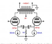
Can you explain how the 6V6s are using garter bias? I can't see it in the schematic.
Here is the principle explained:
Blumlein’s Garter Circuit Revisited
I use TL783 current sources. I will make a drawing later, first to the dentist.
Blumlein’s Garter Circuit Revisited
I use TL783 current sources. I will make a drawing later, first to the dentist.
Jaap,
There is no Garter Bias in your Post # 10533.
And, the only coupling from cathode to cathode is 0.33 uF/2
Two 0.33 uF caps in series (.165 uF) is 9646 Ohms at 100Hz.
With the 2 current sources, the cathodes are free to move separately at 100 Hz, and even more freely at 20Hz. There is no bass response at all, for the schematic that is posted.
There would be very little output from the tubes even at 1kHz.
This would make a good tweeter amplifier from 5kHz to 20kHz.
I know, you just did us a favor by showing the modification, on a simplified schematic, but . . .
How many Newbies will try and modify their working amplifier to copy that simplified schematic?
Last edited:
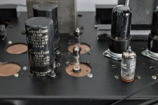
"In addition" implies they are using big electros (1000uF?) as in the picture but bypassed by 0.33u... Is that the case, Jaap?
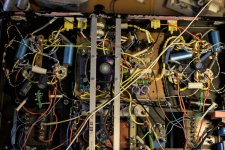
I have come to understand that I do not build in a favored style, that's OK. It works for me ;-))
It works for me! I off-loaded the power supply from the amp chassis to its own chassis a few years ago and I am very happy I did. It is nice to see both the 6N7 and 46 used.
Jaap,
There is no Garter Bias in your Post # 10533.
And, the only coupling from cathode to cathode is 0.33 uF/2
Two 0.33 uF caps in series (.165 uF) is 9646 Ohms at 100Hz.
With the 2 current sources, the cathodes are free to move separately at 100 Hz, and even more freely at 20Hz. There is no bass response at all, for the schematic that is posted.
There would be very little output from the tubes even at 1kHz.
This would make a good tweeter amplifier from 5kHz to 20kHz.
I know, you just did us a favor by showing the modification, on a simplified schematic, but . . .
How many Newbies will try and modify their working amplifier to copy that simplified schematic?
This is what i did
Attachments
Jaap,
Your schematic in Post # 10538 looks like a good circuit.
But as far as I understand the Garter Bias circuit, your schematic of post # 10538 does not use the Garter Bias method.
In a typical Garter bias amp, each individual cathode of the push pull output stage goes to an individual series string of 2 resistors, from the cathode to the top resistor, to the second cathode resistor to ground.The bottom of one tubes grid leak resistor is returned to the junction of the other output tubes series string of the cathode resistors.
As such, each output tube receives bias from the other output tube.
- Home
- Amplifiers
- Tubes / Valves
- Photo Gallery