To OP27 (OPA27) : you're it until you're dead or I find someone better...
In other words, you can stick anything in there and give it a shot, but you'd be hard pressed to convince me, on paper, that there's a better option out there than the OP27.
"To improve the sound, one must first understand the sound." While I also do not believe the OP27 op amps themselves are in any way a bottleneck, it's easy enough to test that hypothesis.
Thought and suggestions (links) welcome.
/rjm
Hi Richard,
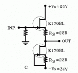
my vote goes for Figure 15C in this pdf but with lower Rs (say 10R). This is basically the B1, but older 🙂 If you chose a trimpot for the lower resistor, you can trim out any output offset. This one is very transparent and might be supplied by simple emitter followers, circumventing your dedicated regs.
I once tried to make something better, it got ridicously complicated and if its really better -- I am not so sure now.
Rüdiger
That pretty much sums up my own thoughts so far, right down to the notion of using a second set of followers for the supply.
There is no particular need to use FETs, but the biasing of the lower transistor becomes a bit more complicated when bipolars are used.
I'm not worried about DC offset as the coupling capacitor would still be on the output, at least for now.
There is no particular need to use FETs, but the biasing of the lower transistor becomes a bit more complicated when bipolars are used.
I'm not worried about DC offset as the coupling capacitor would still be on the output, at least for now.
Attachments
There is no particular need to use FETs, but the biasing of the lower transistor becomes a bit more complicated when bipolars are used.
rjm
For the new version 4 try this (the MC step) in the front..
L C Audio Technology / RIAA/MC Amplifier
on one small board. Then the old Phonoclone3 solo can be the MM unit and Phonoclone + stepup = Phonoclone4 can be the MC unit 😉
Finn
I'm not worried about DC offset as the coupling capacitor would still be on the output, at least for now.
I would place the coup between the 2nd opamp and the buffer: you'll drive the latter starting from zero volts allowing greatest output voltage swing before clipping.
Rüdiger
I would place the coup between the 2nd opamp and the buffer: you'll drive the latter starting from zero volts allowing greatest output voltage swing before clipping.
Rüdiger
True, but remember that the phonoclone has to be "plug and play" as a DIY project, i.e. reliable, low output offset voltage cannot be contingent on things like matching the transistors, or the temperature not going over 30C...
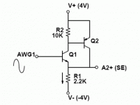
Another variant on the theme, which I dredged up from somewhere or other. It could use the same BD136, BD137 transistors required for the Xreg, so no added complexity to the BOM.
Though frankly the simple emitter follower with resistor loading seems the best option.
Though frankly the simple emitter follower with resistor loading seems the best option.
Attachments
Last edited:
RJM, I remember you said that you feel the best part for the job is OP27, but a guy wonders... 🙂
Why don't you give the LME49710 a try and let us all know how it goes. On paper its rather similar to the OP37, but it is a much more recent design.
Why don't you give the LME49710 a try and let us all know how it goes. On paper its rather similar to the OP37, but it is a much more recent design.
Did you mean LME49710 or the LME49830? Asking since you have linked the other one.
LME49710
http://www.national.com/ds/LM/LME49710.pdf
I had the other document open and copied from the wrong tab.
http://www.national.com/ds/LM/LME49710.pdf
I had the other document open and copied from the wrong tab.
LME49710
http://www.national.com/ds/LM/LME49710.pdf
I had the other document open and copied from the wrong tab.
All four positions on each board? Or am I allowed to combine?
The most effect will be seen in IC1. IC3 and IC4 should be the same type.
No guarantees this chip will be stable in this circuit, either way.
No guarantees this chip will be stable in this circuit, either way.
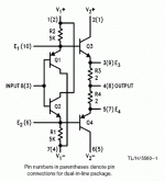
Another buffer, the classic LH0002 from national semi. I read a post someplace where people were complaining about the unavailability of this IC (it is long discontinued) and someone made the correct observation that you could build the discrete circuit with less than a buck of parts.
It's four transistors and four resistors, and the datasheet even goes so far as to supply the resistor values. (its not a simplified schematic, this is really the whole thing)
It'd be overkill for this application, I'm providing it for completion. I've been thinking a lot recently about transistor circuits (as opposed to tubes or op amps) .
Attachments
Musical Fidelity V3 power supply schematic, I want to build my own rather than buy a little dinkie/pinke from scotland. Is there anybody out there?Thanks ♫♪♫♫♫♪
A short note in case anyone tried this... couldn't get it in the search:
Has anyone used SLA batteries instead of the PSU? I already have the PhonoClone 3 in a separate boxes from the CPU. It should be straightforward to just put batteries in another box same size as the PSU so I can swap them.
However, should I bypass the XReg portion to do so?
Has anyone used SLA batteries instead of the PSU? I already have the PhonoClone 3 in a separate boxes from the CPU. It should be straightforward to just put batteries in another box same size as the PSU so I can swap them.
However, should I bypass the XReg portion to do so?
I have used batteries in previous version of the PhoneClone. 2*12V SLA without regulation and 2*18V Ni-MH with regulation.
I do prefer with 15-50 Watt transformer.
I have posted some results earlier. 12V SLA is a little more muffled sound. The 18 V Ni-MH gave a pitch black background, but is "slower" then regular PSU. I did not finish the latest version yet (to many projects on my desk). I do expect the combination of the Regular and Ni-MH: Dark and Fast.
The implementation of a virtual zero circuit, as used in several battery operated headphone amplifiers, did not improve the battery operation. Don't ask me why, it sounds "slower".
Keep in mind that the speaker system I use is either electrostatic mid-high or open baffle; You get hooked on "speed" by those systems.
My 2cts.
Michiel
Hi, would someone be kind enough to plug this info into the BOM calculator... I don't have Excel and would really like to use the results. I've tried just about ever value for R1 and R2 and I'm just making thing worse...
Denon DL-103R Specifications
•Output: 0.25 mV
•Output impedance: 14ohms
Many thanks!!
Denon DL-103R Specifications
•Output: 0.25 mV
•Output impedance: 14ohms
Many thanks!!
R1 14 ohms (10R, 15R or 22R)
R2 560 ohms (anything between 470R and 620R)
Open Office (free) can be used to open and edit the BOM worksheet.
R2 560 ohms (anything between 470R and 620R)
Open Office (free) can be used to open and edit the BOM worksheet.
I tried it and it's lacking a bit of gain and body. Some say that 100 ohms is the idea loading for this cartridge... Taking this into consideration and the fact that I could use a bit more gain what would you suggest?
Many many thanks for all your help you've always been fantastic with support for this project and I for one really appreciate that!
Many many thanks for all your help you've always been fantastic with support for this project and I for one really appreciate that!
Neither R1 or R2 are "loading" the cartridge. R2 sets the gain, R1 balances the cartridge coil resistance. Neither has a huge influence on the sound.
If you want more gain, just drop R2 to something like 220 ohms.
The Phonoclone 3 is by nature slightly on the lean side of neutral.
If you want more gain, just drop R2 to something like 220 ohms.
The Phonoclone 3 is by nature slightly on the lean side of neutral.
- Home
- Source & Line
- Analogue Source
- Phonoclone 3


