Done. No changes. None of the corners/sides raised let it play without skipping. At about 40 degrees tilt it loses focus (about the same in all directions).
Right 🙂 I'm running out of ideas on this...
The wobble on the arm. If it plays OK for 10 minutes or so while its doing that wobble then I think we have to say at this point that that is 'normal' for that machine and that something else is coming into play.
The official Philips alignment procedures are horrendous but if you are thinking of altering anything then I would say this.
1/ The laser power preset should not generally be altered. That setting will affect only the amplitude of the RF.
2/ If you alter any other preset then first of all mark its position visually with a dab from a marker pen on the PCB and wiper contact point.
3/ Generally speaking a player that is working correctly is surprisingly insensitive to misaligned settings. If a setting is on a knife edge then there is usually some underlying issue.
4/ If you alter the focus offset preset then monitor the RF at the same time. I can't find a clear description of what this does. There is mention of focus bandwidth but I would just say monitor the RF and see if the 'Q' or quality/focus changes. If it does adjust for best possible amplitude and diamond shape within the waveform.

The issue seems a tracking problem for me. The test/adjustment procedure is to observe the positive and negative spikes when in Pause mode. The peaks should be of equal amplitude. If not, adjust with the tracking offset variable resistor.
Another check is the focus offset. Measure directly at the output of the focus servo amplifier. It should be around 0 Volts. Check at the beginning an at the end of a disc. If there is gross deviation, rise or lower the spindle motor with the Allen key (not the arm!).
Another check is the focus offset. Measure directly at the output of the focus servo amplifier. It should be around 0 Volts. Check at the beginning an at the end of a disc. If there is gross deviation, rise or lower the spindle motor with the Allen key (not the arm!).
Thanks, Mooly. I'll proceed with care. I will do the measurements that have been suggested above and by @lcsaszar right above first.Right 🙂 I'm running out of ideas on this...
The wobble on the arm. If it plays OK for 10 minutes or so while its doing that wobble then I think we have to say at this point that that is 'normal' for that machine and that something else is coming into play.
The official Philips alignment procedures are horrendous but if you are thinking of altering anything then I would say this.
1/ The laser power preset should not generally be altered. That setting will affect only the amplitude of the RF.
2/ If you alter any other preset then first of all mark its position visually with a dab from a marker pen on the PCB and wiper contact point.
3/ Generally speaking a player that is working correctly is surprisingly insensitive to misaligned settings. If a setting is on a knife edge then there is usually some underlying issue.
4/ If you alter the focus offset preset then monitor the RF at the same time. I can't find a clear description of what this does. There is mention of focus bandwidth but I would just say monitor the RF and see if the 'Q' or quality/focus changes. If it does adjust for best possible amplitude and diamond shape within the waveform.
Your third point again seems to point to a connection/contact/dry solder issue I have overlooked.
I'll somehow get this one going, but it will take some more time. I'll be back with more results, but probably not today. Thanks to all of you guys so far, and please keep watching with what I'll come up.
Could you point to where I should hook the scope to when looking at the spikes in pause mode?The issue seems a tracking problem for me. The test/adjustment procedure is to observe the positive and negative spikes when in Pause mode. The peaks should be of equal amplitude. If not, adjust with the tracking offset variable resistor.
Another check is the focus offset. Measure directly at the output of the focus servo amplifier. It should be around 0 Volts. Check at the beginning an at the end of a disc. If there is gross deviation, rise or lower the spindle motor with the Allen key (not the arm!).
ok so I proceeded a bit. Am not sue if I understood everything you wrote though. At A13 + I get a waveform (see first pic below) which becomes much more choppy and ragged and seems to brake up and away from the fundamental before skipping occurs.You want to monitor radial motor drive at connector A13 (floating ground - do not earth scope on either point) for spikes in output while playing and when paused and trying to nudge the arm manually by tapping with the eraser end of a pencil. If you get any spikes (which you should), they have to go in opposing driver direction. The correction should look like a smooth jump without any noise. If you see noise, proceed to the next step below, otherwise suspect mechanical binding of the arm (suspension and bearing).
When I nudge the arm away, it corrects without a noise, until a threshold, when it makes a noise and actually skips. If I nudge it gently enough that it does not skip, the wave pattern goes up or down on the scrren, according to the direction of pushing the arm.
I cannot judge if I now qualify for that "if" unfortunately 🙂 Ribbon cable check under way. If no fault, proceed to next step.If the tracking correction response is incorrect or sporadically shows up without provocation of the swing arm, first check the ribbon cable next to the arm motor output at A13. These tend to fail on these older units causing all sorts of weird symptoms. One scenario is the intermittent connection causing back EMF of the motor freaking out the error feedback amp.
If that checks ok, look at the error amp output and follow it back until you find the area where weirdness originates from. Thats at A17 pin 3+4 on back to IC6107 and IC6101. You'll need to reference the schematic to pinpoint the exact path from back to front of the arm servo. I recommend trying some freeze spray on the 6 x TO92 transistors to see if theres a reaction. Its going to be tricky playing a CD while trying to measure these hard to reach locations so you'll need to solder some extension cables for this in some cases.
One observation: In tracks (I realize now mostly at the extremities of the disk) where the laser is prone to skip the wave pattern becomes much more ragged.
When hitting pause I get some fleeting extra spikes.
When hitting pause I get some fleeting extra spikes.
profiguy may want to add more details for you 🙂
I see only three presets on the board layout you posted. Laser power, focus gain and tracking offset.
Focus gain usually has a wide a margin. Note where the preset is and give it a turn each way while looking at the RF. Also listen to the noise from the RAFOC. Can you hear any hissing or high frequency white noise. Normally you want the focus gain just below the point where the noise starts to become audible. Keep looking at the RF though and if the pot affects the RF in any way then set it at the point that gives the best quality, amplitude and diamond shape.
Focus gain usually has no obvious effect beyond the points where the disc won't play at all. To low and its prone to skip and be affected by vibration. To high and its noisy (the coils in the pickup).
Tracking offset can usually be set by looking at the tracking error waveform when you perform track jumps (searching from one track to another). In that brief moment the pickup is searching you set the preset to give and equal visual symmetry of the tracking error waveform above and below a notional centre line running through it.
As long as you have marked those presets then don't be afraid to alter them. I would not alter the laser power though as that looks good with the 1.2 volt level you are getting on the RF. If you were to alter that preset then make a note of the disc you are using and measure accurately the RF so that you can use the same disc and set it back where it was.
Hi Mooly, thanks for your perseverance. I also still have some. I admit that I really wanted to tackle the huge heap of work to get done today but find myself again in front of the open player, musing. So your post comes at the right moment.
I had already marked and turned the focus offset pot after the last posts here. It did not give any big effect, not even at the extremes (or maybe I just turned it to one extreme), neither laser sound-wise, nor concerning an effect on skipping. I also measured the laser voltage according to the Philips method, found it too low, set it to the according value in the SM, found the RF voltage far too high and no effect on skipping, so set it exactly back where it was (368mV). I have the Focus gain pot left 🙂
@profiguy : I followed your procedures (in terms of what I understood needed to be done) and now also checked the connections on the drive board. I don't see or measure any broken traces or wires.
The six small signal resistors on the board remain to be tested. There's not much space among them. I did some diode test measurements to find anything sticking out a lot (like a transistor with only open circuit or OL junctions) but only found mildly reassuring measurements. I needed to remove and measure them. Maybe that's a next step. I don't have freeze spray lying around at the moment, it's also awkward to spray from below into the underside of the motor board.
Mooly and profiguy better explained it than I can. This is the radial error voltage at A13 indeed.Could you point to where I should hook the scope to when looking at the spikes in pause mode?
I also measured the laser voltage according to the Philips method, found it too low, set it to the according value in the SM, found the RF voltage far too high and no effect on skipping, so set it exactly back where it was (368mV).
The Philips method is I think bizarre. What it does is look at the photo diode array current (not the laser current) as the laser light is reflected back from the disc onto the array.
Ultimately you always want to see the correct RF level and as the RF level is also directly related to what is reflected back from the disc it seems to me to be the most suitable way to do it. I accept that if the reflected light is low for some other reason (poor alignment internally of the optics or cloudy optics (then it means the laser diode is over run current wise but what else can you do? You have to always end up with the correct RF level for the player to work correctly and as you discovered, trying the official way gave far to high a level 😀
I agree. I read trough the pages 7-1 to 7-8 in the SM and it read like an introductory course in cybernetics. it seems that you need a special academic degree to simply understand what they explain let alone execute the tests. I wonder if anyone ever did. For me it would be a rather steep learning curve.
Deep in work today but not ignoring you. The tracking error waveform is showing a suspect bad component in the swing arm drive (likely a bad op amp or drive transistor) with drifting output and noise over top of the error correcting signal. Suspect one of the TO92 drive transistors or the op amp itself..The error correction signal should be low passed at around 1000hz to only let correction occur in the confines of the 500 - 200 rpm disc speed. Same holds true for the focus error correction. Any more high frequency noise will be coming from the output stage. It shouldn't be that rough looking as you state after the laser is parked when the player is paused and show equal corredtion im both directions as mentioned before. You will usually be able to hear the tracking correction noise coming from the swing arm drive coil. When making an extreme out of parameter adjustment of the focus offset, you will hear noise only when turning the adjustment all the way over to one direction. - this can be normal, but not the spikes showing up after the laser is parked in paused play mode. The swing arm suspension can still be binding though, despite the symptoms pointing to the error amp and outout drive.
Thank you, @profiguy. What an in-depth analysis.
How do you suggest to proceed and where exactly to measure?
There are three op-amps on the motor board (6101, 6107, 6114). I looked at the TO-92 transistors (seven altogether) again yesterday night. Stared at them, actually, from both sides.
I found that 6118 had a bad solder joint. I cleaned it, re-soldered it – moment of hope! –, but no change. It had probably still made enough contact. Could not detect more cold joints in the board. Before resoldering the lead with the cold joint I checked 6118 in place with a component tester and it showed ok.
See pic attached. hFE is VERY low at 4. Alltransistors gives a minimum of 40 for the type used, BC635. I only really realize this discrepancy this morning.
As the tester showed me a functional transistor, I left it. But maybe the low hFE is a track to follow? Or can it be an artefact due to testing in-circuit?
It seems that the next step would be to test the remaining six TO-92's and measure voltages at the pins of the op-amps. Is there somewhere to look for on the decoder board as well?
As the skipping is irregular (and only ever forward) and I don't have a total breakdown of the player, I still think in the direction of an intermittent contact somewhere. But maybe a leaky silicon device can give that picture, too. I can also get freeze-spray for diagnosis, btw, only will need some time.
I'll really have to immerse myself more deeply in work, too, today. Thanks for finding the time to reply and keep with the search, @profiguy !
Last edited:
I had already stared at that motor PCB many times without finding any cracked joints. This time I had to bend the TO-92 slightly in order to get the measuring tips to its leads, and then one of the leads broke through its solder joint on the underside of the board. This is how I discovered the spot.
hFE of 4 instead of more than 40 seems pretty suspicious too me now.
hFE of 4 instead of more than 40 seems pretty suspicious too me now.
Last edited:
Of the transistors you measured, am I hearing you correctly that 6118 measured only 4 for gain? Thats suspect, but if measured in circuit can generate strange results. Best way would be to desolder and check out of circuit. You also want to see a slight climb in gain when warming the transistor. Being the problem is intermittent in nature, warming and cooling specific components will potentially reveal the issie. You can also try swapping the low hfe transistor for another one. Bottom line is if the tracking error drifts while the player is paused, there's a problem and its not normal. The servo can compensate up to a point but once out of bounds it will keep going. Again, you want to see equal corrections being made under correct operation. If you could post the rest of the servo block schematic for tracking, I can tell you which components to look at. These single beam pickups use rf amplitude delta to adjust tracking. If you have a CD with a radial track error, you'll see the swing arm move exactly with the disc's eccentricity. Single beam CDMs are known for their ability to track very well when working correctly, far better than most 3 beam pickups, mainly due to the swing arm's fast response time.
Thanks profiguy.
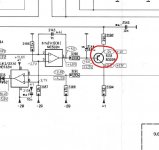
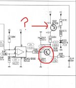
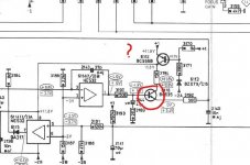
Yes. 6118 measured only 4 for gain in circuit. If I swap it, would a BC649 do? That's what I have here at the moment, but maybe also some other ok substitutes. BC649 has lower voltage etc ratings, but the position in circuit seems not too demanding. see the two pages from the SM which show the circuit attached. unfortunately the scan put it on two pages. 6118 is at H8 on the upper image.
I don't completely understand your statement "Bottom line is if the tracking error drifts while the player is paused". It does not skip while paused, continues exactly where I paused it, and the wave pattern in pause looks very much like in play, only with those intermittent high spikes. Is that what you are referring to?
Out of circuit 6118 has a hFE of 173. Seems pretty normal.
Would have been too nice to find a culprit 🙂
Would have been too nice to find a culprit 🙂
Just mentioning this because......
The only transistor I have had fail intermittently on these is the one supplying the laser diode. Trying to think back.... its like 30 to 35 years ago now... and I'm sure I've had this more than once. As I say, just mentioning it because... I'm trying to think of the fault and it was something weird.
Typically Philips and there are lots of variations. All have the laser driver but others also switch the rail and one even switches the supply to the opamp.
Attachments
- Home
- Source & Line
- Digital Source
- Phillips CD 204 skipping 3 years after rebuild