tubee said:Get a beer 😀 😀
Good guess but no, that's what I'm about to do.
I installed a 5V super regulator on the decoder chip. This has taken detail levels from ~70% to 90% of my old CD63 with good mods. But this player does vocals and piano (and others) in a more convincing way...
It's LOADS more open and 3-D 😎
Simon
SimontY said:
Good guess but no, that's what I'm about to do.
I installed a 5V super regulator on the decoder chip. This has taken detail levels from ~70% to 90% of my old CD63 with good mods. But this player does vocals and piano (and others) in a more convincing way...
It's LOADS more open and 3-D 😎
Simon
Just arrived in sunny donny Simon, Got my beer and well what can I say. That 5v reg on the decoder should have a retail price in excess of £500 lol
Now you know why I was smiling all day!
😀
Yes guessed that but you allready posted the answer. I was reading back and found their site. Unfortunately the don't sell outside usa. How did you get them?
http://www.referenceaudiomods.com/Merchant2/merchant.mvc?Screen=CTGY&Store_Code=RAM&Category_Code=SR
I should compare it with my few-euro shunt but..
Consuming a pint now btw😀 😀
http://www.referenceaudiomods.com/Merchant2/merchant.mvc?Screen=CTGY&Store_Code=RAM&Category_Code=SR
I should compare it with my few-euro shunt but..
Consuming a pint now btw😀 😀
tubee said:Yes guessed that but you allready posted the answer. I was reading back and found their site. Unfortunately the don't sell outside usa. How did you get them?
http://www.referenceaudiomods.com/Merchant2/merchant.mvc?Screen=CTGY&Store_Code=RAM&Category_Code=SR
Did you check out http://www.audioupgrades.co.uk/ use the contact link and ask Brent or contact Simon directly. Use their SPower regs they are IMHO better!
They are worth every penny (at least twice!)
Ian
I bought them second hand cheaply. They're not really worth buying new (too pricey). Audiocom-uk sell them anyway.
Simon
Simon
An externally hosted image should be here but it was not working when we last tested it.
And:
An externally hosted image should be here but it was not working when we last tested it.
Have a good look, It is a simple opamp regulated (TL071) transistor, maybe it can be copied 😎
tubee said:
Have a good look, maybe it can be copied 😎
Trust me, it's not worth it. These units are tidy. The guy who runs the show couldn't be any more helpful.
If you try to copy, you may well succeed but, on veroboard 3 times the size???
You'll never beat the quality.
It makes that much difference to the sound, it'll be the best £40 you ever spend on the player!!!!
IMHO!
I can do a lot, but maybe a tick bigger then that PCB. Yesterday soldered 6 smd R's on a perfboard (but the schematic didn't work, YET 😀 ) I found out with a good layout it is possible to make things very small even on perfboard
Will try the s reg in time.
Will try the s reg in time.
I'd not personally copy Brent's design, he's a good friend, and I know for a fact he sells these for a tiny profit margin. It's nearly a standard application-note circuit anyway - it's the parts and layout that make the S-power superb.
Back to the CD650 - got Carol Kidd on (after a couple of pints) and the sound is wonderful. The biggest change is the treble, which is now very clean and not recessed anymore.
Simon
Back to the CD650 - got Carol Kidd on (after a couple of pints) and the sound is wonderful. The biggest change is the treble, which is now very clean and not recessed anymore.
Simon
SimontY said:I bought them second hand cheaply. They're not really worth buying new (too pricey). Audiocom-uk sell them anyway.
BTW, when I made this comment, I meant they're not worth the RRP next to S-powers, which are a much better design. They can handle ~6amps as opposed to 300mA of Super Reg. They also use more carefully selected parts. And you can bolt a heatsink on properly LOL
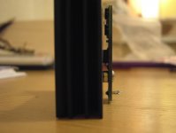
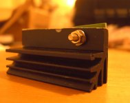
Attached is a pic of how I got a heatsink aligned with the Super Reg earlier this evening..
Simon
Attachments
S-Regs on 7210 decoder
Simon, Ian and ..... Did you include the RAM chip's supply in the reg upgrade? And with Oscons or Tants, too? Incidently, those CPU cooler clips can easily be "rebent" to act as "chip clips" (sorry!) with insulating sleeves, and there is also some heat conducting "gel" that's sticky.That 7220 chip (o/sampler, filter, spdif o/p) is incredibly noisy and I added a seperate 0V wire back to the P/Supply centre 0v, if I remember correctly Last nights posts reminded me to add that "my observations" (well, i have to make my"poking about" sound impressive, no!) are concerning the NOS setup here and so, may not work the same for you that are still using that incredibly noisy o/sampler, filter, spdif o/p 7220 menace - sorry! I think I used a seperate 0V wire back to the P/S central 0v at one point but can't remember the difference - then dumped the chip for NOS and added the p/supply 2nd shunt reg system to "chip groups" (servo, decoder, others) - seperate one for the display - all a bit of a spagetti mess, but works okay - low noise floor.
Simon, Ian and ..... Did you include the RAM chip's supply in the reg upgrade? And with Oscons or Tants, too? Incidently, those CPU cooler clips can easily be "rebent" to act as "chip clips" (sorry!) with insulating sleeves, and there is also some heat conducting "gel" that's sticky.That 7220 chip (o/sampler, filter, spdif o/p) is incredibly noisy and I added a seperate 0V wire back to the P/Supply centre 0v, if I remember correctly Last nights posts reminded me to add that "my observations" (well, i have to make my"poking about" sound impressive, no!) are concerning the NOS setup here and so, may not work the same for you that are still using that incredibly noisy o/sampler, filter, spdif o/p 7220 menace - sorry! I think I used a seperate 0V wire back to the P/S central 0v at one point but can't remember the difference - then dumped the chip for NOS and added the p/supply 2nd shunt reg system to "chip groups" (servo, decoder, others) - seperate one for the display - all a bit of a spagetti mess, but works okay - low noise floor.
This pic doesn't really show much but it looks cool! I stuck a plastic cable-tie-attacher (dunno what these are really called) to the bottom of the 'sink. This spaces it off the board. Obviously the aluminim is conductive and connected to the output (+5V) so it mustn't touch any metal. It's held upright by a cable tie, fastened to a smoothing cap nearby.
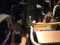
Ground and output wires are quite short. It's interesting to note that in the CD650 the 7210 is additionally decoupled on its power pin (pin 40) by an inductor (green thing).
Simon
Ground and output wires are quite short. It's interesting to note that in the CD650 the 7210 is additionally decoupled on its power pin (pin 40) by an inductor (green thing).
Simon
Attachments
Shunt reg for SAA7220
Shunt Reg for 7220
Hi Tubee,
Thanks for you earlier replies.
I am still building the shunt reg for SAA7220 and have made my own small PCB. (Its taking a while because I don't have enough time at the moment)
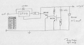
I have added a gyrator to the input, as described by Martin Clark in post #68 in this thread and post #6569 in the Marantz CD63 & CD67 mods thread. The gyrator uses a BC547C to drive a BC139 with RC filtering 33K resistor and 1.0uF film cap.
These should be my last two questions before completing and installing the shunt reg:
1. How critical is the value of the Oscon cap at the +5V out. e.g. can I use a 47uF which I have on hand?
2. The reg will be mounted within 6cm of the 7220 Vin pin. Do I need both the output cap on the shunt reg and the bypass cap on the 7220 (47uF Rubycon ZL) or I need to remove one or the other.
This shunt reg will replace a simple 317 based reg I have I previously installed. It feeds only the 7220 and has its own PSU and transformer secondary (a bit of overkill).
Thanks
Shunt Reg for 7220
Hi Tubee,
Thanks for you earlier replies.
I am still building the shunt reg for SAA7220 and have made my own small PCB. (Its taking a while because I don't have enough time at the moment)
I have added a gyrator to the input, as described by Martin Clark in post #68 in this thread and post #6569 in the Marantz CD63 & CD67 mods thread. The gyrator uses a BC547C to drive a BC139 with RC filtering 33K resistor and 1.0uF film cap.
These should be my last two questions before completing and installing the shunt reg:
1. How critical is the value of the Oscon cap at the +5V out. e.g. can I use a 47uF which I have on hand?
2. The reg will be mounted within 6cm of the 7220 Vin pin. Do I need both the output cap on the shunt reg and the bypass cap on the 7220 (47uF Rubycon ZL) or I need to remove one or the other.
This shunt reg will replace a simple 317 based reg I have I previously installed. It feeds only the 7220 and has its own PSU and transformer secondary (a bit of overkill).
Thanks
47uF oscon is a good choice for the 7220.
Use the bypass cap at the 7220, not on the reg's output. That's because you want to bypass the noisy 7220 as directly as possible - if you have a cap further away (1)some of the noise will be radiated from the larger loop and (2) that cap won't be very effective anyway.
Use the bypass cap at the 7220, not on the reg's output. That's because you want to bypass the noisy 7220 as directly as possible - if you have a cap further away (1)some of the noise will be radiated from the larger loop and (2) that cap won't be very effective anyway.
martin clark said:47uF oscon is a good choice for the 7220.
Use the bypass cap at the 7220, not on the reg's output. That's because you want to bypass the noisy 7220 as directly as possible - if you have a cap further away (1)some of the noise will be radiated from the larger loop and (2) that cap won't be very effective anyway.
Hi Martin and thanks for your reply.The reg I am building is the shunt reg posted by Tubee in post #26 on this thread. He shows a 10uF cap at the +5V output of the shunt (see attachment) I take your points 1 and 2 above, but I just want to be clear in my own mind that your comments about the caps apply to tubees shunt reg schema.
Thanks,
Joe
PS: Would a higher power and high gain darlington like BD681 (hFe 750) work for the gyrator, and would the 33k/1uF RC be OK?
Attachments
Yes, definitely leave the oscon at the chip and remote from the shunt; the trace of wiring resistance will help stabilise the reg that way, too.
Your ideas for the 'gyrator' should work a treat, but watch the voltage drop.
With Hfe of 750, and a current draw of about 200mA, the darlington will need a base drive current of at least 0.26mA. Through 33Kohm that means a voltage drop across the gyrator of 0.26mA * 33K, + 1.4v for the darlington vbe drop - or about 10volts total! That also means the darlington would be dissipating several watts. Perhaps drop the R to 3k3 - not as effective at low frequency, but fine at filtering HF noise which is what the thing's for.
This is why a compound of transistors can be better - much higher total hfe means lower voltage drop, and less power wasted.
martin clark said:Yes, definitely leave the oscon at the chip and remote from the shunt; the trace of wiring resistance will help stabilise the reg that way, too.
Your ideas for the 'gyrator' should work a treat, but watch the voltage drop...
I have 10.84V available so it should be OK.
...This is why a compound of transistors can be better - much higher total hfe means lower voltage drop, and less power wasted.
I will stay with the BC547/BD139 darlington for the gyrator and get on with it.
Thanks again Martin.
Joe
Re: S-Regs on 7210 decoder
I've got one reg on the filter and one on the rest of the board (3 chips inc the decoder). Not sure what they do they are small. Could well be RAM chips???
I may split out on the filter board further but it will only be with std regs for the time being
😎
jameshillj said:Simon, Ian and ..... Did you include the RAM chip's supply in the reg upgrade? And with Oscons or Tants, too?
I've got one reg on the filter and one on the rest of the board (3 chips inc the decoder). Not sure what they do they are small. Could well be RAM chips???
I may split out on the filter board further but it will only be with std regs for the time being
😎
- Home
- Source & Line
- Digital Source
- Philips CD650 mods