Re: DOS output stage
Ian, a few weeks ago I set out quite on the same road. I have a CD471 I was modding (exactly smae schematics), and started off with a passive ItoV conversion - a 51 ohm resistor. Then I made the
forst opamp by having it still in the inverting mode like the classic I/V : now with 1k65//42k. The 42 k needs a capacitor in parallel othersise the opamp starts to break down. I have 82 pF but rather it might need 147 pF. This goes into the second opamp in the standard +1 follower mode with compensation - the compensation is meant for some effects of the SAA7220 if I am correct.
I n parallel: I connected a discrete "Opamp", the Hiraga pre-amplifier, with 2SK240 in the first stage, the same set of resistors (1k65 being non inductive Allen Bradley), and here a 150 pf mica+470 ohm damper across the 42k feedback path. Without this roll-off it is hard to listen to; with is now extremely mellow to listen to.
I can compare the two by switching around.
I like the discrete one just a few percent more.
Alberti
UV101 said:Guys
I want to move my DOS (based on Ray's design on the cd63/67 thread) into my CD960.
The 63 has a voltage output DAC and the DOS attaches straight to it.
I believe I need more gain from the I/V stage (1st opamp) in order to drive directly into the DOS.
Can anybody see what I need to do to get a little bit more from the 1st stage?
I'd really appreciate any help. I don't need specific values, just know which ones to change! 😕
Cheers Ian
Ian, a few weeks ago I set out quite on the same road. I have a CD471 I was modding (exactly smae schematics), and started off with a passive ItoV conversion - a 51 ohm resistor. Then I made the
forst opamp by having it still in the inverting mode like the classic I/V : now with 1k65//42k. The 42 k needs a capacitor in parallel othersise the opamp starts to break down. I have 82 pF but rather it might need 147 pF. This goes into the second opamp in the standard +1 follower mode with compensation - the compensation is meant for some effects of the SAA7220 if I am correct.
I n parallel: I connected a discrete "Opamp", the Hiraga pre-amplifier, with 2SK240 in the first stage, the same set of resistors (1k65 being non inductive Allen Bradley), and here a 150 pf mica+470 ohm damper across the 42k feedback path. Without this roll-off it is hard to listen to; with is now extremely mellow to listen to.
I can compare the two by switching around.
I like the discrete one just a few percent more.
Alberti
Joe: try a slightly lower current resistor @ LM317 for more current to the shunt. Mine are under 5V too, no problem i guess but only thing could be that the rise time can be some slower from the lower voltage powered logic outputs.
The last opamp of standard output schematic from cdp can be omitted, i did that with the cd880. Used 4 cinch output connectors and can swap buffered/non-buffered.
The first opamp is the I/V, the 2nd only a buffer and extra filter. You get an voltage offset then probably.
The last opamp of standard output schematic from cdp can be omitted, i did that with the cd880. Used 4 cinch output connectors and can swap buffered/non-buffered.
The first opamp is the I/V, the 2nd only a buffer and extra filter. You get an voltage offset then probably.
This thread's racing along again!!
I dropped my new Taiwanese TDA1541A N2 in a couple of days ago. If there's any difference it's very subtle and what I hear I couldn't swear by.
That said it seems just a fraction more detailed with a little more oomph at both frequency extremes. Fine for the money spent.
More to come soon, though I'm more working on my new open baffles 😀
Simon
Simon, and all,
When you do these mods, it's often quite difficult to clearly discern changes and you can easily end up going round in circles.
However, if you use good headphones ( + a known h/amp) as a reference, many of the difficulties are avoided and is much easier, and quicker, to make progress.
With the 1541A chip, the decoupling caps (approx 100nF) have a direct relationship to the DEM oscillator freq (about 200kHz) set by the 470pF cap. A 5% change in this value (+/- 20pF) will clearly alter the balance of the sound.
It is also quite clear that disc ceramic caps at this quite critical point aren't the best choice of components - suggest use high quality caps like good propylene, or better still, styrene.
Don't know if the above applies the same with the 1540, or 1541 (no A) but there should be a significant difference in the sound of your new N2 chips - perhaps you are "loosing the sound" somewhere else.
As size may be a problem with the decoupling caps, can probably only fit box propylene ones here, but choose the best you can find that will fit, even if the leads are a bit longer than ideal.
Hey guys, been very busy lately so not had much time to post.
Now that my cd94 is working again after replacing the blown main tx with various toroids, in the next few days I'll be playing around with dac decoupling caps, trying various kinds (Box polyprop, Mundorf MKP etc) against my current PPS types. I'll be sure to keep you all updated on my findings.
Cheers, Lee.
James,
Thanks for the great words of wisdom. I can hear changes quite well on my system, although I do agree it might be clearer on headphones. However, this is not my regular reference as I don't like headphone listening and don't have a good 'phones amp yet.
My mk2 open baffle speakers will most certainly be very revealing (waveguide tweeter, 8" PA mid, 2 x 12" bass, 24mm BB plywood baffle etc.) so all the little changes will be even easier to hear.
The N2 does seem better, but I've gone from TDA1541A to TDA1541A N2 - it's (on paper) pretty much the same chip. It's not as if I've put an S1 or S2 in. I'd expect a bigger change with these.
I've ordered a 'styrene cap for the DEM pins, and I will report.
I plan to order 1uF PPS caps for decoupling soon - they seem like a good compromise on price, size and specification. Still, I'll be very interested to hear what Lee has to say after some testing on his '94.
Cheers,
Simon
Hi Guys, Like Lee, I've been off line and busy!
1st I've got the DOS in and working so thank you all (too many with usefull comments to name!) Its connected as Andy suggested into pin 2&3 of the 2nd opamp (which is obviously removed!!)
I haven't tried to change the gain through the I/V stage yet but hopefully I will tomorrow as the output is down on what it should be.
I've now managed to get my 63 back in working order (rebuilt O/S stage (completed rays mods in this area), LMExxx20 in tin hat, PSU and SPower in Analogue DAC, same psu with std reg for 2xclocks, Black gates, and ZA's sprinked) and in a back to back the 960 seems well behind in treble and poss clarity but miles in front on low end accuracy,analogueness & umph! Overall i prefer the 960 by a long way but i'm a little dissapointed that it appears to be so far behind in the clarity dept. I hope I'm mistaking some high freq suppression for clarity??
I've spoken to Lee and he has pointed me in the direction of the bit's n pices around the I/V stage. Funnily enough, Andy has also suggested that the DEEM area is not required and reading between the lines, it's going to suppres the high frequencies. I'm gonna hook it all out and do another comparison when I introduce the pot for incresding the I/V gain.
I've also introduced some hum! I'll look arond for earth problems, failing that I'll teach it the words!!!

I'll keep you updated, any suggestions (contructive of course🙄 ) greatly appreciated.
Simon, when I spoke to Lee about the DAC change, he has suggested that it could well be one of those changes that at first appear to be very minimal but if you change back, you'll know why you upgraded!!
Ian
1st I've got the DOS in and working so thank you all (too many with usefull comments to name!) Its connected as Andy suggested into pin 2&3 of the 2nd opamp (which is obviously removed!!)
I haven't tried to change the gain through the I/V stage yet but hopefully I will tomorrow as the output is down on what it should be.
I've now managed to get my 63 back in working order (rebuilt O/S stage (completed rays mods in this area), LMExxx20 in tin hat, PSU and SPower in Analogue DAC, same psu with std reg for 2xclocks, Black gates, and ZA's sprinked) and in a back to back the 960 seems well behind in treble and poss clarity but miles in front on low end accuracy,analogueness & umph! Overall i prefer the 960 by a long way but i'm a little dissapointed that it appears to be so far behind in the clarity dept. I hope I'm mistaking some high freq suppression for clarity??
I've spoken to Lee and he has pointed me in the direction of the bit's n pices around the I/V stage. Funnily enough, Andy has also suggested that the DEEM area is not required and reading between the lines, it's going to suppres the high frequencies. I'm gonna hook it all out and do another comparison when I introduce the pot for incresding the I/V gain.
I've also introduced some hum! I'll look arond for earth problems, failing that I'll teach it the words!!!
I'll keep you updated, any suggestions (contructive of course🙄 ) greatly appreciated.
Simon, when I spoke to Lee about the DAC change, he has suggested that it could well be one of those changes that at first appear to be very minimal but if you change back, you'll know why you upgraded!!
Ian
I've only heard about 4 players with the TDA1541 DAC and none had quite as good treble as good as a well sorted CD63KI (Lee's '94 was by far the closest). But so what? They make better music when modded. My 650's starting to show some good treble, however, and with some new tweaks (mostly already discussed) I'll be expecting it to get even better. To-do:
* separate PSU / winding for C1 clock
* 'styrene cap on de-emp pins of DAC
* 1uF PPS chip caps on DAC decupling
* -5V and -15V S Powers on DAC
* tx & PSUs to go with above DAC regs
* dual Burson discrete op-amps
* upgrade resistors around op-amps
* os-cons at decoder and digital filter psu pins
* coax bypass from filter signal to DAC input (possibly)
* 1541A S1 or S2 upgrade
* C1 clock buffers/dividers to feed TDA1541 and SAA7210 separately
* re-house on plywood board w/IEC socket and good mains lead
* psu diodes all changed to HEXFRED types
* need to look at resistor/cap filters between chipset, maybe adjust
* change digital filter to 'B' version (as in CD94 etc.)
* look at servo, HF amp and psu caps around CDM2 mech and upgrade - remember the servo upgrades were VITAL in the CD63 for treble detail and articulation / clarity
* transport mods and LED bath
Something in there will make the treble completely come out 😀
Simon
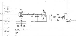
De Emphasis!
Just removed the Deem parts of the circuit!
I seem to have lifted again! Loads more treble detail and the whole sound seems much more punchy!
Def recommended if you've got similar DEEM circuts on the I/V stage.
Removed
C580-585
R562-565
Q556&557
Diagram attached again for ease.
Ian
😀
Just removed the Deem parts of the circuit!
I seem to have lifted again! Loads more treble detail and the whole sound seems much more punchy!
Def recommended if you've got similar DEEM circuts on the I/V stage.
Removed
C580-585
R562-565
Q556&557
Diagram attached again for ease.
Ian
😀
Attachments
I think, just removing the FET would've had the same effect.
But, I thought very few recordings would trigger deemphasis to be on anyway, so this circuit wouldn't be switched on.
But, I thought very few recordings would trigger deemphasis to be on anyway, so this circuit wouldn't be switched on.
Re: De Emphasis!
Phil.
Correct.
It is the difference in the frequency response between having the FET "ON" or "OFF" which gives the deemphasis.
Ian.
The C's and R's are required to give the desired overall filter response along with the components between the opamps.
It will give better treble but in fact you may now have a peak or at least a rising response.
Ideally, you should model the filter response without these components to see what you've got.
Andy
UV101 said:
Removed
C580-585
R562-565
Q556&557
philpoole said:I think, just removing the FET would've had the same effect.
But, I thought very few recordings would trigger deemphasis to be on anyway, so this circuit wouldn't be switched on.
Phil.
Correct.
It is the difference in the frequency response between having the FET "ON" or "OFF" which gives the deemphasis.
Ian.
The C's and R's are required to give the desired overall filter response along with the components between the opamps.
It will give better treble but in fact you may now have a peak or at least a rising response.
Ideally, you should model the filter response without these components to see what you've got.
Andy
Re: Re: De Emphasis!
I guess I need to scope the output if the I/V stage and look for clipping?
I certainly dont seem to hear any
Ian
poynton said:
Ian.
The C's and R's are required to give the desired overall filter response along with the components between the opamps.
It will give better treble but in fact you may now have a peak or at least a rising response.
Ideally, you should model the filter response without these components to see what you've got.
Andy
I guess I need to scope the output if the I/V stage and look for clipping?
I certainly dont seem to hear any
Ian
Re: Re: Re: De Emphasis!
I wouldn't think clipping would be a problem.
The output is supposed to be 2v rms so with 15-0-15v rails, there should be plenty of headroom.
The filter response is supposed to be level to 20khz and then roll off sharply.
most of that will be the bessel (or whatever) filter between the opamps.
the components you removed would probably give a falling response with a couple of knees. Now the first opamp is linear.
As I said, ideally it needs modelling.
Interestingly, other TDA1541A DACs on the forum do seem to dispense with the filter altogether e.g.. i/v resistor and tube buffer.
Maybe Thorsten's designs may help?
Andy
UV101 said:
I guess I need to scope the output if the I/V stage and look for clipping?
I certainly dont seem to hear any
Ian
I wouldn't think clipping would be a problem.
The output is supposed to be 2v rms so with 15-0-15v rails, there should be plenty of headroom.
The filter response is supposed to be level to 20khz and then roll off sharply.
most of that will be the bessel (or whatever) filter between the opamps.
the components you removed would probably give a falling response with a couple of knees. Now the first opamp is linear.
As I said, ideally it needs modelling.
Interestingly, other TDA1541A DACs on the forum do seem to dispense with the filter altogether e.g.. i/v resistor and tube buffer.
Maybe Thorsten's designs may help?
Andy
I've still got the filter on the input of the 2nd opamp (which is now the dos). The only components removed were on the 1st opamp.
There is a filter on the DOS as well.
Like you say, I need better equipment than I have here to see what its up to.
All I can say is it sounds very good!
There is a filter on the DOS as well.
Like you say, I need better equipment than I have here to see what its up to.
All I can say is it sounds very good!
OK to go against the above, I've just removed all the filters other than whats on the DOS.
My I/V is just an op amp and resistor across 2&6. this is feeding directly into the DOS. The differential input of the DOS is now at ground.
What a difference as in "night" and "day".
The detail is absolutley awesome. This morning the 63 was in front for detail now its miles behind.
I've not detected any adverse effects what soever but I'm now hearing details Ive not heard before.
The 10th note of stairway to heaven is distorted. Its only just detectable on the 63, its clear as can be on the 960!
now i'm really smiling, I've almost considered post a pic of my smile!!😀
Def worth investigating guys
Ian
OK, Ian..
the next logical step would be to remove the DOS ?
then try to connect the DOS only in place of the opamp ?
Andy
the next logical step would be to remove the DOS ?
then try to connect the DOS only in place of the opamp ?
Andy
I think I need the 1st op amp to do the I/V conversion?
I'll get the player on my pals kit he uses to measure THD and the like to see if I've buggered anything but I'm def hearing a dramatic inprovement.
I think Lee's 94 is in a pretty similar condition so far as the O/P stage goes from the I/V directly into the DOS.
Ian
I'll get the player on my pals kit he uses to measure THD and the like to see if I've buggered anything but I'm def hearing a dramatic inprovement.
I think Lee's 94 is in a pretty similar condition so far as the O/P stage goes from the I/V directly into the DOS.
Ian
Thomo said:Hi Andy,
I tried both of those ideas, and got massive distortion both times.
Cheers, Lee.
What? Massive distortion just using the first opamp and no DOS ?
Using the DOS for I/V would require a suitable low ohm resistor at the DAC output to replace the "virtual ground" of the opamp input.
Andy
- Home
- Source & Line
- Digital Source
- Philips CD650 mods