Hello everybody!Attached diagram of my output stage...
UV101 I have a question. I saw at your diagram you youse the Burson for I/U conversion. It is behind a TDA1541 or a 1541 "A"? Have you any problems there with the Burson?
The Burson is a nice buffer, but since i try a lot i was not able to let him work in the I/U behind my non "A" ...
Maybe can you measure the voltage across pin 4 and 8 at your Burson?
greets, Andreas
Hi Andreas, I currently have the "non-A" version of the dac used with Burson for I/V and haven't experienced any issues.
Cheers, Lee.
Cheers, Lee.
Hello everybody!
UV101 I have a question. I saw at your diagram you youse the Burson for I/U conversion. It is behind a TDA1541 or a 1541 "A"? Have you any problems there with the Burson?
The Burson is a nice buffer, but since i try a lot i was not able to let him work in the I/U behind my non "A" ...
Maybe can you measure the voltage across pin 4 and 8 at your Burson?
greets, Andreas
Hi Andreas,
pin8 is not used as it is a single burson not dual. Both myself and Lee (Thomo) have used single opamp (now Burson) for I/V then straight to the phono output sockets. The rails are at +/-12v. Without the CCS on the DAC output, you will require DC blocking caps on the output.
On the cd650, its a dual opamp configuration. The 1st part of the opamp does the I/V with feedback (same as my diagram) the 2nd opamp is a buffer. Check my diagram against the CD650's. The 1st opamp stage should look similar (-the deem circuit in fact!🙂)
Ian
I decided to take my CD650 apart today. I've totally stripped it down and cast aside the plastic chassis in favour of a 24mm plywood board. I've removed the draw from the CDM2/10 and trimmed some of the plastic off to save space. This is going to be a biiiig rebuilding job, but the player's totally outgrown the standard box.

Here guys, prepare to laugh:
I need to feed my display with 2x1.7vac ct. My tx is 2x7vac. How do I reduce that to 1.7vac?
Lee.
I need to feed my display with 2x1.7vac ct. My tx is 2x7vac. How do I reduce that to 1.7vac?
Lee.
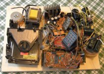
I only just started reading this thread, but I'll post a pic of what I've done so far:
Mounted everything on a sturdy sand-filled plywood base. Added a tube output (SRPP using a 6211 with a 28 ohm I/V-resistor).
Recently I got rid of the loading mechanism and turned it into a toploader. It sounds much better than stock, I was surprised about the last mod!
An externally hosted image should be here but it was not working when we last tested it.
Mounted everything on a sturdy sand-filled plywood base. Added a tube output (SRPP using a 6211 with a 28 ohm I/V-resistor).
Recently I got rid of the loading mechanism and turned it into a toploader. It sounds much better than stock, I was surprised about the last mod!
Last edited:
Nice job!
Can you tell more about that last mod? Maybe some links?
Matthieu
Thank you Matthieu, this is only an experimental set-up 😉
The top-mod is very straight forward, turn the tray mechanism upside down, undo the 2 screws holding the metal clips, bend aside the piece of plastic holding the cdm in place (the plastic has become brittle over the years, watch out, mine broke off..) and you can take it out. I took out the screws holding the small pcb under the cdm, got some longer screws to mount it on a piece of wood and screwed that to the base. (with rubber rings in between to protect the pcb)
Here's another pic:
An externally hosted image should be here but it was not working when we last tested it.
- Home
- Source & Line
- Digital Source
- Philips CD650 mods