Motional feed back amp with some chenges
Hello friends
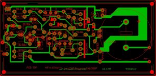
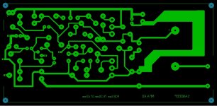
I try to create my first Layout in sprint layout. I attach files with this post. give yours thought on following PCB layout for MFA 40w.
Hello friends
I try to create my first Layout in sprint layout. I attach files with this post. give yours thought on following PCB layout for MFA 40w.
Attachments
40 watt philips amp
1. this amp really sounds great , i made this circuit in year 2005, and use the power 60v,10,ampere current,but i used 2n3773,but the problem i faced was at the near end of the volume , a hiss sound starts and the transistors becomes hot I do not know why.
2. I also have that books some photo copies printed by bombay.
3.I have made many amps,like stks,tip142/147,and many more but the quality i really felt is in philips 40w circuit,
4.this circuit is very famous in india and i think every hobbiest made this amp,
5. I even repaired 6-7 amp,but i really seen and observed that all those amps were made in 0-36v supply,not by 0-60 to draw actual power,
6.I used every care to maintain the actuality of the circuit,so i used 1% rated resistors and good quality components .
NOTE : IF anybody have the solution of that problem than help me or you have any other good circuit which sound like this 40w phillips,than please tell me ,
my email id : usualfellow@yahoo.co.in
dear sir,
i also have made this circuit in 1987.pcb was from vega kit from bombay.when i set preset predriver transistor bc557 became warm and destroy.it doesnt produse 40 watts.
i also have made this circuit in 1987.pcb was from vega kit from bombay.when i set preset predriver transistor bc557 became warm and destroy.it doesnt produse 40 watts.
hi all ,this is usual fellow here, please tell who ever tried this philips 40 watt amp with 60volts supply for 40 watt out put. and what are the feed back of yours about this amp ,if any body have any other amp circuit which is reliable , please tell me about that also my email id is usualfellow@yahoo.co.in
Construct SYMASYM amp. There is a thread here with all the details.
Search 'explendid amplifier'
Gajanan Phadte
Search 'explendid amplifier'
Gajanan Phadte
Hi... I first made this amplifier in 1988, along with the preamp and 55V unregulated supply. This amp has excellent sound, and is very durable. Used it for 15 years without any problems until I finally misplaced it while moving house.
After years of searching, I was able to get the complete kits (PCBs and components) for the amp and preamp a few months ago. I have made it again (running on 50 V unregulated supply). It sounds great as ever.
I also got the PCB of the 60V regulated supply ( without components/transformer) and hope to make it soon.
Details of the kits:
1. Got them from Visha electronics (Mumbai, India)
2. Excellent quality of components (all resistors are 5%)
3. Included instructions which are reasonably good.
4. Amp kit included the heat sinks and mounting kits for the output transistors
I placed the order through email, made the payment by bank transfer, and received the kits in Delhi in 2-3 days
Cost Details:
1. Power amp (stereo) - Rs. 770
2. Preamp - (stereo) - Rs. 280
3. 60V Regulated Power Supply (PCB Only) - Rs. 50
4. 54V 3A transformer ( very good quality GURU brand) is available from Lajpat Rai Market (Delhi). Price is Rs. 2300
I am attaching the Visha catalog, which also has the contact details
Attachments
I'm willing to ride this shure amplifier liked this nbf system amplifier stage coupled by a transformer. It's good?
http://cdn.shure.com/user_guide/upload/1827/us_pro_va302_ug.pdf
http://cdn.shure.com/user_guide/upload/1827/us_pro_va302_ug.pdf
Hi ricardo M2 is not a trasfomer , M2 is a reverb unit
See this:
https://www.google.com.ar/search?ne......1c.1.64.img..13.9.2134.Z80ZJ8RmZg0#imgrc=_
See this:
https://www.google.com.ar/search?ne......1c.1.64.img..13.9.2134.Z80ZJ8RmZg0#imgrc=_
Dear Reji,
your observations are matching with mine. I have also built several designs, both for pre and power amps, and always dissatisfied. i never could get that sweet sound which i got with these units.
Hence after building all these and junking them. I fell back on these designs, with the 25Watt power amp, very happy again. Just like you at one time I was mulling a valve amp also, but dropped it.
i think the major difference is the high voltage supply and the single transistors operating nicely in the linear region over a wider range, and may be the slew rate also. But my experiments with LF series High slew rate amps also did not satisfy me. seeing as your post was old, I thought, you may still see my reply.
will be posting more shortly.Cheers
Nmosfet
Hi all,
The Philips 40W amplifier is an excellent amplifier by all standards. I first made it in 1991. Later I scrapped it thinking it is an old design, and tried newer discrete DIY amps like the Zen and the P3A (ESP), and IC amps using the STK IC. I also tried active filters (eg. the 4th order Linkwitz-Riley) to improve the sound. Finally, after all these years I assembled the Philips amp once again, and have come to the following conclusions:
(a) The sound from the single supply, capacitor coupled Philips amp is better than the other well respected dual supply, direct coupled, DIY amps I have tried. This is despite the use of a electrolytic cap at the input, a quasi-complementary configuration for the output devices (which by the way, are the humble 2N3055s in my amp), an electrolytic cap at the output, and specified 0.8% THD at max output power . The amp has heavy bass, open midrange and sweet highs. No ear fatigue at all even after prolonged listening.
(b) this amp works very well with a simple 6th order passive filter at the output (ie, woofer connected directly and tweeter connected through a capacitor - I used two-way speakers). No need for high order passive filters or active filters.
(c) I had made the Philips Universal preamp in 1991, and according to my memory, it was an excellent match to the 40 W amplifier.
It may be noted that I used a heavy transformer (350 VA) with a total of 10,000 microFarad filter capacitance for powering the amp. I ran the P3A with the same devices for comparison.
I think what makes this amp special is its single transistor input (as opposed to the differential inputs found in the newer amps). According to Rod Elliott (ESP) such amps have a higher bandwidth and slew rate: see his article "El Cheapo".
This amp taught me something else as well: CDs and even 128 kbps MP3 files can sound excellent, if you have the right amp. I was all set to buy a turntable and build a tube amp, but after hearing the Philips amp I am not too sure whether i should embark on that project now..
If any of you want the amplifier schematic along with the article (taken from "Audio Amplifier Systems" (3rd Edn.) 1972, written by Mr. Hull from Philips, Netherlands - I have a copy of the book, and it is a priced possession!) please email me to philipreji@gmail.com.
cheers,
Reji
Hi nmosfet,
Saw your post only now..
The relatively high supply voltage provided to the active devices - which will definitely reduce nonlinear operation - is probably one reason for the quality of this amp. I think most of the vintage SS amps had this feature, along with loads of power, which gave them that "authoritative" sound. The so-called "current feedback" topology employed also may be important. Another point is that even though the amp is rated at 40 W per channel most people will play it only at 4W (half volume) or less, which further reduces nonlinearities.
I'm still using the 40 W power amp (unfortunately I lost the universal preamp board but I'm planning to build it again - these two match each other wonderfully). Occasionally I use a 15+15 band equalizer before the amp. I was very wary of using an equalizer because in theory the phase will get totally messed up (particularly with so many bands in each channel), but in practice it has made the amp just sound better through my speakers, in my room.
The circuit certainly stands for some criticism on theoretical grounds, but in practice it sings very well!
cheers,
Reji
universal preamp
Hi Reji,
Thanks for the reply. really that is what i thought, about the high voltages. and it really sings very well. but it is so laborious to build, compared to some chip amps, but I invite your comment, on why the chip amps do not sound convincing, whenever you find time? nice knowing you.🙂
best.
Nmosfet.
Thanks nmosfet.
According to my understanding chipamps will not be as linear as discrete amps when the current draw from the amp is high (this could very well be due to mechanical limitations in the manufacture of ICs). Chipamps should be fine for the input and voltage amplification stages, but if used for current amplification stage, the linearity of the amp can get compromised. Nonlinearity will result in harmonic and intermodulation distortion. While the former is somewhat ok (and sometimes pleasing) to the ears, the latter is certainly not. On the other hand the discrete amp designer has all the freedom to choose high voltage and high current active devices, particularly for the power stage (and even parallel them), which will operate in the linear regime even if the amp is taxed within reasonable limits.
Of course discrete amps are more laborious to build but as we know the trouble is worth it..
cheers,
Reji
K163 kit
I would really love to buy that Kit stereo k163 with the power regulators and the preamp .
But how ? I can't find them on their web site.
where can I get those schematics from?
Gabe
QUOTE=rmalik;4138578]Hi... I first made this amplifier in 1988, along with the preamp and 55V unregulated supply. This amp has excellent sound, and is very durable. Used it for 15 years without any problems until I finally misplaced it while moving house.
After years of searching, I was able to get the complete kits (PCBs and components) for the amp and preamp a few months ago. I have made it again (running on 50 V unregulated supply). It sounds great as ever.
I also got the PCB of the 60V regulated supply ( without components/transformer) and hope to make it soon.
Details of the kits:
1. Got them from Visha electronics (Mumbai, India)
2. Excellent quality of components (all resistors are 5%)
3. Included instructions which are reasonably good.
4. Amp kit included the heat sinks and mounting kits for the output transistors
I placed the order through email, made the payment by bank transfer, and received the kits in Delhi in 2-3 days
Cost Details:
1. Power amp (stereo) - Rs. 770
2. Preamp - (stereo) - Rs. 280
3. 60V Regulated Power Supply (PCB Only) - Rs. 50
4. 54V 3A transformer ( very good quality GURU brand) is available from Lajpat Rai Market (Delhi). Price is Rs. 2300
I am attaching the Visha catalog, which also has the contact details[/QUOTE]
Last edited:
PCB layout
Hi All,
I want to try to build this amplifier. Anyone who have a PDF file?
Thank you in advance.
Regards,
Boyet
Hi All,
I want to try to build this amplifier. Anyone who have a PDF file?
Thank you in advance.
Regards,
Boyet
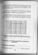
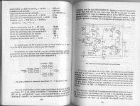
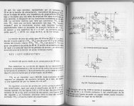
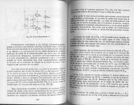
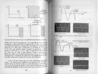
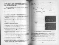
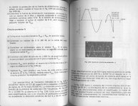
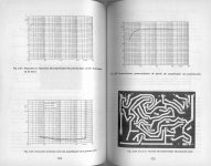
I try to attach here the full article, scanning the Spanish translation of the book "Audio amplifier systems".
Attachments
-
 pg139.jpg215.8 KB · Views: 1,040
 -
 pg140-141.jpg468.7 KB · Views: 982
 -
 pg142-143.jpg398.1 KB · Views: 970
 -
 pg144-145.jpg480 KB · Views: 882
 -
 pg146-147.jpg357.9 KB · Views: 812
 -
 pg148-149.jpg378.9 KB · Views: 450
 -
 pg150-151.jpg373.3 KB · Views: 411
 -
 pg152-153.jpg353.9 KB · Views: 548
 -
 pg154-155.jpg374.4 KB · Views: 692
great job pabloso, thank you in the name of all who were interested in this old old amplifier.
i was around 14 when i had that book(english version ) in my hands, and for some reason i always thought thats a great amplifier. Now i can try it , i have no excuse not to do it.
i was around 14 when i had that book(english version ) in my hands, and for some reason i always thought thats a great amplifier. Now i can try it , i have no excuse not to do it.
Hi pabloso, great work.
Just *one* extra demand, can you scan the PCB page with a couple rulers drawn on the page, vertical an horizontal, so an accurate 1:1 PCB can be made?
Or give us the exact PCB size.
Preferrably not a .jpg but a .gif or .png
Thanks.
Just *one* extra demand, can you scan the PCB page with a couple rulers drawn on the page, vertical an horizontal, so an accurate 1:1 PCB can be made?
Or give us the exact PCB size.
Preferrably not a .jpg but a .gif or .png
Thanks.

I know these kinds of Philips amps. The design is almost "standard" for the era, and it has been applied, with minor alterations, in many commercial products too. And they sound absolutely nice!! Especially in the 22RH720 receiver where the powerstage is partially operating in class-A.
I though have one question about the schematic in this thread: C3, the bootstrap capacitor, in the schematic is only 32uF, whereas in most schematics I know the value is at least 470uf or even 1000uf... so, couldn't there be a minor glitch in the schematic of this particular amp?
I though have one question about the schematic in this thread: C3, the bootstrap capacitor, in the schematic is only 32uF, whereas in most schematics I know the value is at least 470uf or even 1000uf... so, couldn't there be a minor glitch in the schematic of this particular amp?
- Home
- Amplifiers
- Solid State
- Philips 40/25/15 watts amplifier with Universal preamplifier circuit.