my dear DIY brothers
this is regarding a circuit developed by Philips in 1970's. it is a 40/25/15 watts amplifier with Universal preamplifier circuit. it was very popular in DIY groups at that time. it use to give a very good quality of sound, eventhough it was a AC coupled amplifier. originally the output transistors are BD182. but most of the people used with 2n3055.
do anybody have the circuit diagram. i got some printed circuit boards without circuit diagram.
regards
renjish
Those who had the diagram are now in their late fifties and don't login at DIYAUDIO.com. They have enough problems of their own and will definately not take the trouble to scan the diagram and post it here.
To make the story short, dump that over 3 decade old pcb, search the net and make yourself a new design power amp.
2N3055 is an old transistor by design and does not sound good. There are many that sound good and are easy to install.
Go to the site sound.westhost.com and u will find preamp circuits that will work equally good.
Gajanan Phadte
a (much) better regard for things Philips here
http://forum.mfbfreaks.nl/
http://www.mfbfreaks.nl/
38
http://forum.mfbfreaks.nl/
http://www.mfbfreaks.nl/
38
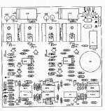
Yes..it has condenser output, also it has tone controls and vol control
mounted in a single board....also the ballance and supply...a complete stereo...low powered old unit from Philips.
My mail is:
panzertoo@yahoo.com
regards,
Carlos
mounted in a single board....also the ballance and supply...a complete stereo...low powered old unit from Philips.
My mail is:
panzertoo@yahoo.com
regards,
Carlos
Attachments
Encourage yourself...
to assemble something better or learn the hard way. When u compare this with the never products, only then u will know the reality.
This circuit was sunding good in seventies.
It is good to see DestroyerX has put up the circuit details. He is always and ever-ready to help.
But...
from your post I get it that just because u have the PCB, u want to assemble it. Remember in today's standards, this circuit stands nowhere. One reason is that it uses a single supply which needs an output capacitor for coupling the speaker.This sounds bad. I can see other reasons also but I am not competent enough to explain.
Select a good sounding circuit depending on your power requirement and go for it.
If u are in metro, it is easy to get a quality pcb made or make yourself one with the toner transfer method.
Or simply draw the tracks on a laminate using nail polish/oil paint and etch it.
Learning whichever way is better than not-at-all.
Gajanan Phadte
I still have this amp in working condition,& i can provide ckt diagram if required.
my email id is suppal005@redifmail.com
my email id is suppal005@redifmail.com
Hi
I am planning to make home theater with philips transistorised circuit with unversal pre ampifier,
already i had made home theater with TDA2020 with 741 pre amp
Pl suggest me will phillips transistorised amp will provide me the excellent detailed sound quality as compared to other amps? or can any one suggest me which one i can do.
my mail id is
www_vinoth@rediffmail.com
In Argentina this circuit has named "Fapesa".
Schema and layout is here: Tecnicosaurios.com • Ver Topic - Amplificadores FAPESA.
The file is "70.pdf"
Registration is needed, but is free.
P.D Sorry for my bad english...
Schema and layout is here: Tecnicosaurios.com • Ver Topic - Amplificadores FAPESA.
The file is "70.pdf"
Registration is needed, but is free.
P.D Sorry for my bad english...
Very unkind we need to register to read
Some foruns are doing this way to force us to register... a pity that, i do the opposite, no way to accept that demand....that forum does not make a friendly presentation to our communitty.
I know that you are not the forum owner hermano, but these guys should understand that they may be loosing members this way.. something goes covering text...very annoying, very rude.
Good are foruns where we do not feel the management presence, not to feel alike a fish inside a glass pot, beeing observed, controled (moderated)... alike a prisoner watched by cameras.
Saludos brasilênos hermano Sudamericano.
Carlos
Last edited:
Hi Vinoth,
You will be happy building amps like Symasym, DX, Apex, Techno and many more compared to the old philips.
Hi Renjish,
Let me know if you still need the philips circuit diagram. I can arrange to scan and post it...
You will be happy building amps like Symasym, DX, Apex, Techno and many more compared to the old philips.
Hi Renjish,
Let me know if you still need the philips circuit diagram. I can arrange to scan and post it...
Sorry, i tried upload the file, but the system no allowed this file size.
Now, i upload on "Rapidshare" this file without mark water:
http://rapidshare.com/files/457122103/Philips_Universal.pdf
My intention is help us. I am fan of vintage electronics too...
Best regards.
Now, i upload on "Rapidshare" this file without mark water:
http://rapidshare.com/files/457122103/Philips_Universal.pdf
My intention is help us. I am fan of vintage electronics too...
Best regards.
Hi all,
The Philips 40W amplifier is an excellent amplifier by all standards. I first made it in 1991. Later I scrapped it thinking it is an old design, and tried newer discrete DIY amps like the Zen and the P3A (ESP), and IC amps using the STK IC. I also tried active filters (eg. the 4th order Linkwitz-Riley) to improve the sound. Finally, after all these years I assembled the Philips amp once again, and have come to the following conclusions:
(a) The sound from the single supply, capacitor coupled Philips amp is better than the other well respected dual supply, direct coupled, DIY amps I have tried. This is despite the use of a electrolytic cap at the input, a quasi-complementary configuration for the output devices (which by the way, are the humble 2N3055s in my amp), an electrolytic cap at the output, and specified 0.8% THD at max output power . The amp has heavy bass, open midrange and sweet highs. No ear fatigue at all even after prolonged listening.
(b) this amp works very well with a simple 6th order passive filter at the output (ie, woofer connected directly and tweeter connected through a capacitor - I used two-way speakers). No need for high order passive filters or active filters.
(c) I had made the Philips Universal preamp in 1991, and according to my memory, it was an excellent match to the 40 W amplifier.
It may be noted that I used a heavy transformer (350 VA) with a total of 10,000 microFarad filter capacitance for powering the amp. I ran the P3A with the same devices for comparison.
I think what makes this amp special is its single transistor input (as opposed to the differential inputs found in the newer amps). According to Rod Elliott (ESP) such amps have a higher bandwidth and slew rate: see his article "El Cheapo".
This amp taught me something else as well: CDs and even 128 kbps MP3 files can sound excellent, if you have the right amp. I was all set to buy a turntable and build a tube amp, but after hearing the Philips amp I am not too sure whether i should embark on that project now..
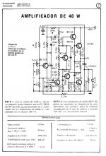
If any of you want the amplifier schematic along with the article (taken from "Audio Amplifier Systems" (3rd Edn.) 1972, written by Mr. Hull from Philips, Netherlands - I have a copy of the book, and it is a priced possession!) please email me to philipreji@gmail.com.
cheers,
Reji
The Philips 40W amplifier is an excellent amplifier by all standards. I first made it in 1991. Later I scrapped it thinking it is an old design, and tried newer discrete DIY amps like the Zen and the P3A (ESP), and IC amps using the STK IC. I also tried active filters (eg. the 4th order Linkwitz-Riley) to improve the sound. Finally, after all these years I assembled the Philips amp once again, and have come to the following conclusions:
(a) The sound from the single supply, capacitor coupled Philips amp is better than the other well respected dual supply, direct coupled, DIY amps I have tried. This is despite the use of a electrolytic cap at the input, a quasi-complementary configuration for the output devices (which by the way, are the humble 2N3055s in my amp), an electrolytic cap at the output, and specified 0.8% THD at max output power . The amp has heavy bass, open midrange and sweet highs. No ear fatigue at all even after prolonged listening.
(b) this amp works very well with a simple 6th order passive filter at the output (ie, woofer connected directly and tweeter connected through a capacitor - I used two-way speakers). No need for high order passive filters or active filters.
(c) I had made the Philips Universal preamp in 1991, and according to my memory, it was an excellent match to the 40 W amplifier.
It may be noted that I used a heavy transformer (350 VA) with a total of 10,000 microFarad filter capacitance for powering the amp. I ran the P3A with the same devices for comparison.
I think what makes this amp special is its single transistor input (as opposed to the differential inputs found in the newer amps). According to Rod Elliott (ESP) such amps have a higher bandwidth and slew rate: see his article "El Cheapo".
This amp taught me something else as well: CDs and even 128 kbps MP3 files can sound excellent, if you have the right amp. I was all set to buy a turntable and build a tube amp, but after hearing the Philips amp I am not too sure whether i should embark on that project now..
If any of you want the amplifier schematic along with the article (taken from "Audio Amplifier Systems" (3rd Edn.) 1972, written by Mr. Hull from Philips, Netherlands - I have a copy of the book, and it is a priced possession!) please email me to philipreji@gmail.com.
cheers,
Reji

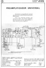
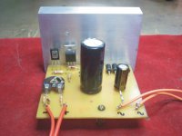
The sound is a bit bright, but balanced enough to be an old design.
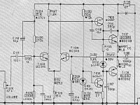
The 2N3055 was built in 1982 but BC548/549 are current and have been selected for gain (hFE> 500).
I could not get the BC108/109 nor BD182 ...
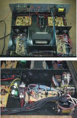
The power supply is stabilized (not that you can see in the picture), but the sound has a very small buzz, I am working to remove it.
Photo and schematic of the power supply (not the original design):
The 2N3055 was built in 1982 but BC548/549 are current and have been selected for gain (hFE> 500).
I could not get the BC108/109 nor BD182 ...
The power supply is stabilized (not that you can see in the picture), but the sound has a very small buzz, I am working to remove it.
Photo and schematic of the power supply (not the original design):
Attachments

my dear DIY brothers
this is regarding a circuit developed by Philips in 1970's. it is a 40/25/15 watts amplifier with Universal preamplifier circuit. it was very popular in DIY groups at that time. it use to give a very good quality of sound, eventhough it was a AC coupled amplifier. originally the output transistors are BD182. but most of the people used with 2n3055.
do anybody have the circuit diagram. i got some printed circuit boards without circuit diagram.
regards
renjish
Its pcb along with circuit is sold by 'vegakit' in india.I have the package,will try to post in some days.
I think BD182 is not available anymore. I used an unregulated power supply of maximum 70 VDC output (when unloaded). When the amp was running the voltage was around 65 VDC. This amp seems to have a small hiss: probably due to its relatively higher bandwidth.
The quasi-complementary output stage in the original design is a trade-off due to the much higher cost of PNP power transistors in the early seventies. The situation being different now, what about using a true complementary configuration for the output stage (pairing 2N2955 and 2N3055)? Will it make the sound even better?
cheers,
Reji
Hi
There are several aspects to this old circuit which can be improved with a little tweaking. I also built this circuit but didn't like the sound much compared with a Bailey. Main reasons are due to the large roll-off capacitor on the base of the VAS (22 nF); and using slow BD182 (can use 2N3055). If you use a complementary pair (2N3055/MJ2955) you can improve the output stage and reduce crossover distortion. Negative feedback should not be taken from the loudspeaker: use a 1.5k directly from the mid-rail. Maybe this was an attempt to improve the bass response with a small output capacitor. Use a bigger output capacitor: modern computer grade capacitors with low ESL and ESR will probably allow 10mF in the space of an old 1.6 mF and give much better bass and not cause undue distortion.
I found that the high input impedance using 150k resistors gave a lot of LF noise. You can reduce this by using a pair of bias resistors (say 27k from tap to + and 22k from tap to GND) and a 22k from the mid point to the base of the input PNP. Use a 10 to 100 uF capacitor from the mid-point to ground to filter the supply line.
FInally, change the HF bias by removing the 27 pF and 22 nF slow-down caps. Replace the 390 pF by a 220 pF and bypass the 220 ohm series resistor; use a 220 pF capacitor between the pnp base and GND to make sure the base impedance is always low and change the overall frequency comp capacitor to 220 pF as well.
You will find that you have a very good amp with these mods which gives less than .01% THD at 20 kHz and negligible crossover using a CP output.
Last edited:
If anybody has a philips amp and want to restore it or like to go vintage, then it is fine.
If not, don't waste your time on these not-good-sounding designs.
Amps have their sound. U will not understand it if u assemble only one or two amps.
If u want to assemble a chip amp, go for TDA7294 or some other TDAxxxx
If want a good sounding amp with good net support, assemble a Symasym or there is a new design exclusively for DIYers on this forum
Gajanan Phadte
Last edited:
- Home
- Amplifiers
- Solid State
- Philips 40/25/15 watts amplifier with Universal preamplifier circuit.