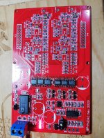
Stage 2 voltage
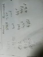
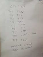
These are my measurements
L9 /1R 17 mv
C57 3.56v
R56 4.8v
R65 4.6v
R70 4.6v
It is a bit higher than expected at R56.
The 17 mv across L9 /1R is ok without filter attached?
These are my measurements
L9 /1R 17 mv
C57 3.56v
R56 4.8v
R65 4.6v
R70 4.6v
It is a bit higher than expected at R56.
The 17 mv across L9 /1R is ok without filter attached?
Attachments
R56 is intentionally set to a slightly higher voltage than the other two so you're good. When an I2S clock is supplied that 4.8V will fall to be similar to the other two.
Yes 17mV is absolutely fine without filter attached. You're good to solder in the opamps.
Yes 17mV is absolutely fine without filter attached. You're good to solder in the opamps.
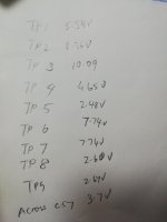
What does TP7 measure? Has it changed from earlier? Also TP1 looked a bit low as if an opamp was loading it. Has it gone back to its target value after fixing Q20?
Last edited:
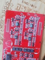
TP7 is the point of interest now, along with TP1. I see a splash of solder between R55 and R68 which is a concern.
TP7 at 7.8V is promising, not very different from TP6. TP9 is still at 10V? Check voltage drop across R66 to see if the AD744 is functioning correctly - it should be about 5mV.
TP7 at 7.8V is promising, not very different from TP6. TP9 is still at 10V? Check voltage drop across R66 to see if the AD744 is functioning correctly - it should be about 5mV.
Last edited:
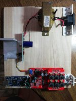
Watchout fro leakage between mains trafo and filter inductors. Why not put the traf and stab into an own box and get it away a few meters from the DAC.
//
//
A few meters distance isn't necessary - I regularly have an EI transformer around 50cm from my DACs without any noticeable hum.
Got music! No hum.
I gives me great satisfaction as this project involves the most amount of smd soldering in my diy hobby.
The handholding by Richard is very comprehensive, prompt and l am very impressed.
I was interested in this project right from the beginning of the discussion in long lingdac thread.
Thank you to Richard and several others in the forum.
Very pleased for you 🙂 Thanks for the feedback and hope you enjoy the music. If you have any comments about how the DAC sounds do leave them here.
- Home
- Vendor's Bazaar
- PhiDAC hex kits with pre-built filters