To my surprise, this simulation ran quite quickly. I guess Derk Reefman's vacuum tube model is not as computationally heavy as I was imagining!I feel you about the aging hardware, on my laptop i sometime use older versions of programs that run better....
It probably helps a lot that I'm running a Linux, not heavy and slow Windows 10.
-Gnobuddy
Thanks for your simulation, Gnobuddy!
I think your results support my assumption in #38 (GNFB via the 1st triode only in Fender's circuitry).
Best regards!
I think your results support my assumption in #38 (GNFB via the 1st triode only in Fender's circuitry).
Best regards!
(But why doesn't the 2nd harmonic distortion cancel out in the push-pull output stage? It's a simulation, so everything is perfectly matched.)
-Gnobuddy
How about running a plot with 82k and 100k plate resistors for kicks?
Sure thing, you got it! Screenshot attached.How about running a plot with 82k and 100k plate resistors for kicks?
Leo-feedback seems to do even less with the LTP with unbalanced anode loads. There is less (fewer dB) reduction in second-harmonic distortion when Leo-feedback is implemented.
-Gnobuddy
Attachments


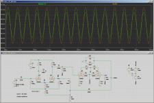
The attached screenshot shows that the signals at U2 control grid, and U2 cathode, are not the same size.Thanks for your simulation, Gnobuddy!
I think your results support my assumption in #38 (GNFB via the 1st triode only in Fender's circuitry).
Best regards!
(I added a DC offset of 1.9 volts to the U2 grid voltage trace, to make it easier to compare the two, since the quiescent cathode voltage is about 1.9 volts more positive than the control grids.)
Since V(u2k) and V(u2g) are not equal by any means, there is a net voltage difference across U2 grid and cathode, and so U2 is definitely also amplifying, and responding to the feedback signal. Not just U1.
If we look at it a little more deeply, U2 cathode has about half of the input signal applied to it (as usual in any balanced LTP), plus about 4% of the NFB signal. U2 grid, meantime, has the full NFB signal applied to it.
This means that the AC component of Vgk of U2 looks like {(0.5*Vinput + 0.04*Vnfb) - Vnfb)}, which simplifies to {0.5*Vinput - 0.96*Vnfb}
(I've neglected an overall minus sign, so if we're fussy, Vgk(u2) is {0.96*Vnfb - 0.5*Vinput} rather than the other way around.)
In other words, it's not just U1 processing the feedback - U2 is involved too, and the only difference from a proper textbook NFB is that the feedback signal to U2 has been reduced by about 4%.
(The "4%" number was from my quick back-of-the-envelope calculation in an earlier post on this thread, based on the fraction of the signal that makes it through the 22k tail resistor and appears at U2 cathode. It won't be exact, but the crucial point is that it is a few percent, not 100 percent - the entire NFB signal does not appear at the shared cathodes. And therefore there is net feedback acting on U2 as well as U1.)
-Gnobuddy
Attachments
Perfect, thank you !
If it's not bothering you can you try the 165 feedback version ?
And coffee please. 😀
Actually I'm craving a cup of coffee right now. The fast-food stores and cafeterias near my workplace are all closed. No coffee. 🙁And coffee please. 😀
-Gnobuddy
If I have some energy left when I get home after work tonight, I'll see what I can do. 🙂If it's not bothering you can you try the 165 feedback version ?
-Gnobuddy
Actually I'm craving a cup of coffee right now. The fast-food stores and cafeterias near my workplace are all closed. No coffee. 🙁
-Gnobuddy
What a shame, many of our places are in business for take out, think we are starting with limited capacity indoor eating.
The circuit in AA864 was originally a "mistake" that became very popular and copied by other makers because it adds even harmonic distortion that most people prefer to the undistorted sound. The effect is similar to that from the Aphex aural exciter. The effect is particularly valuable in a bass amp because it gives a too-mellow bass some bite.
I've heard this legend many times before, which is the main reason why I took the time to put together an LTSpice simulation...."mistake"... adds even harmonic distortion that most people prefer...
And the result? The simulation shows no evidence to support this belief. It appears very likely that this story is a myth. Leo's mistake was just a mistake, an unimportant one that does nothing audible to the sound, but it may have been made out of convenience, allowing him to continue using old-stock turret boards made before the Bassman schematic was revised.
A simulation is better than a verbal myth - I'll take the results of the LTSpice simulation over anecdotal claims any day. But a real experiment with a real Bassman would be even better. If anyone has a access to an actual Bassman, a PC, and some sound-card based audio analysis software, this would be a pretty easy thing to prove one way or the other.
Incidentally: if Leo really wanted more harmonic distortion, he should not have used negative feedback at all! Why would someone introduce NFB, removing much of the existing THD, and then try to re-introduce THD by screwing-up the way the NFB is applied? It doesn't make logical sense to me. (And there is no evidence that Leo knew enough about electronics to understand any of this.)
Also, if Leo wanted more even-harmonic distortion, he should not have used an LTP phase splitter, which cancels out even harmonic distortion!
The Bassman power amp appears to have been an entirely typical Hi-Fi (or "Adequate-Fi" as Merlin Blencowe put it) design of its time, probably lifted entirely from the RCA tube catalogue.
Looking at the results of the simulation, it appears clear now that there was more distortion from the Bassman preamp than the Bassman power amp - particularly from the badly-but-serendipitiously-screwed-up DC-coupled cathode follower.
That second screw-up did actually introduce lots of even harmonic distortion into the preamp, and was quite possibly responsible for much of the Bassman's rise to popularity.
I wonder about other possible reasons for the initial popularity. Perhaps the Bassman was the right size, weight, and loudness for the time. Perhaps they were cheap on the second-hand market, because they made terrible bass guitar amplifiers! 🙂
-Gnobuddy
I do wish we could send coffee to each other. Stay well.
These 1%-0.3% THD numbers are for 2 Watts? That's not what a Bassman is for. 40, 50, 60 Watts (yes, gross clipping).
I also recall that load impedance mattered. While a full speaker-sim is tedious, a 4/40 Ohm switch would fair-model the two extremes (200-600Hz versus 90Hz thump and >3KHz screech).
These 1%-0.3% THD numbers are for 2 Watts? That's not what a Bassman is for. 40, 50, 60 Watts (yes, gross clipping).
I also recall that load impedance mattered. While a full speaker-sim is tedious, a 4/40 Ohm switch would fair-model the two extremes (200-600Hz versus 90Hz thump and >3KHz screech).
.....The Bassman power amp appears to have been an entirely typical Hi-Fi ....probably lifted entirely from the RCA tube catalogue....
I've studied nearly all the enthusiast amps and many of the Professional amps from RCA. Nothing like this. (Probably just as well; many of the plans RCA published seem to have been designed around Free Tubes.) It's not G.E. or Fisher or Pilot neither.
The Schmitt splitter was well-written-up in this period. The too-many NFB attempts seen in the Tweed/XFace period were all common practice.
There is a VERY similar amplifier from anOTHER brand a few years before. But that spoils your Leo-story.
BTW, Leo had others designing amps by the time the Bassman came out. Granted that Leo was a strong presence (he-he). Like Henry Ford, even when he didn't design the product, he had to approve.
Thank you! At least we can send good wishes to each other. 🙂I do wish we could send coffee to each other. Stay well.
(And puzzle over ancient tube-amp trivia to keep the neural synapses engaged during crazy-pandemic-lockdown-economic-collapse madness.)
Fair enough!...2 Watts? That's not what a Bassman is for. 40, 50, 60 Watts (yes, gross clipping).
Keep in mind, I have no idea how accurate the Spice tube models are deep into clipping. Apparently some of the popular pentode / tetrode models (Koren, etc) are very inaccurate at predicting screen grid current under heavy drive.
The Derk Reefman models I'm using are supposed to be much better than some of the other models out there when it comes to generating anode curves. But screen current under hard clipping? I have no idea how close to reality that is.
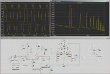
That said, here is the same sim, just at the threshold of clipping. About 34 volts peak-to-peak into 4 ohms, or a hair under 40 watts RMS. Plenty of harmonic spikes at about 40 dB below the fundamental, so a few to several percent THD if you add them up.
And? If we believe the sim, at 40 watts output, there are still no visible benefits to Leo-feedback (or Leo's-amp-tech feedback). Green and yellow-brown traces almost overlap perfectly, both for waveform and FFT. (If you can't see a green trace at all, it means the yellow-brown trace overlaid it perfectly, hiding it from view.)
I think I had better post the actual LTSpice simulation file (.asc), otherwise I might spend the rest of my life running new variations on the Leo-feedback theme. 😀I also recall that load impedance mattered. While a full speaker-sim is tedious, a 4/40 Ohm switch would fair-model the two extremes (200-600Hz versus 90Hz thump and >3KHz screech).
The attached .zip file is my LTSpice .asc file zipped up for online forum software compatibility. If .asc is also legal, I'll attach that too, unzipped and ready to open in LTSpice.
I'm also attaching the Derk Reefman LTSpice vacuum tube models, zipped up for compactness. Unzip this into the same directory (folder) as the .asc file, so that LTSpice can find it when you run the simulation.
By all means, anyone interested, please feel free to load up the .asc file in your copy of LTSpice (a free download), and twiddle away. Maybe we'll all learn something new. If not, it will keep the synapses firing a little more frequently. 🙂
-Gnobuddy
Attachments
Well, I'd say it was a damn sight more'n a FEW......an awful lot of very fine guitarists consider the old Bassmans to be the best guitar amp ever made. But you haven't time to recognize this, as your exhausting position as Chairman of the Leo-Fender-Bashing-Committee must take up most of your spare moments......😛But a few blues guitarists (who did want distortion) found out that the Bassman worked very well for blues guitar, and so, quite by accident, the Bassman went on to become an iconic guitar amp........there is no evidence that Leo knew enough about electronics to understand any of this..........If I have some energy left when I get home after work tonight, I'll see what I can do. 🙂-Gnobuddy
Easy there, Silver! I was talking about the start of the Bassman-as-guitar-amp movement. They weren't marketed to guitarists at first, so it probably started with *one* bluesman who found a second-hand or pawn-shop Bassman at an affordable price, because bass players wouldn't touch the things once they discovered they destroyed speakers and didn't produce much bass doing it. Or maybe it was the only amp left in the music store, because bass players stayed away from it, and it wasn't marketed to guitarists at that point in time.Well, I'd say it was a damn sight more'n a FEW...
That's your take-away from this thread?But you haven't time to recognize this...
How many times have you heard the tale of the magical-Fender-mojo feedback scheme in the Bassman? We just put together some pretty convincing evidence that the feedback scheme was either a mistake, or a deliberate mis-connection to allow re-using old turret boards. It has no magic, and no mojo; it does nothing good, and nothing bad; it's the steering wheel that points sideways when your car is driving straight ahead, irritating, but of no real consequence one way or the other.
We may not have killed the myth, but at least we bloodied its nose a bit. In the process, we got a little closer to reality, to the truth.
To me, getting rid of myths and getting closer to understanding reality is always worthwhile. In many ways, it's been the central core of my entire life. At worst, myths and superstitions hold back humanity and cause suffering. At best, they keep people ignorant and encourage them to make decisions based on emotion, not logic. This is not a very good way to live.
So in my world, trying to dispel myths is not only a basic part of living an honest life, it's also a way of making the world a slightly better place. Find the truth as best you can, share it with other people, make the world slightly better. That's the recipe.
And that's why I spent a few hours putting together a simulation of the supposedly magic part of the Bassman, because I wanted to find out the truth. Not because I have a crusade against Leonidas Fender (I don't), but because I didn't believe this particular claim, and because it is the sort of thing that holds back people from, perhaps, making a better guitar amp design. While we're rushing about mis-wiring feedback loops, hunting for ancient decrepit paper-in-oil capacitors, and making blood-sacrifices of white pigeons to Leo Fender's ghost, we're not learning anything useful about how to build a better amp.
-Gnobuddy
I actually AGREE with you that the NFB scheme used on this particular Bassman appears to be an error! As you pointed out, it really doesn't DO much at all! But this is NOT the Fender Bassman that is so revered by guitarists world-wide----THAT would be the 5F6A---generally regarded as the best sounding of all the Bassman amps. It has a quite different NFB scheme, coupling it with a 5K "Presence" control. Oh, and BTW, according to amp guru Gerald Weber:Easy there, Silver! I was talking about the start of the Bassman-as-guitar-amp movement......How many times have you heard the tale of the magical-Fender-mojo feedback scheme in the Bassman? We just put together some pretty convincing evidence that the feedback scheme was either a mistake, or a deliberate mis-connection to allow re-using old turret boards. It has no magic, and no mojo; it does nothing good, and nothing bad.Gnobuddy
"Contrary to popular belief, Leo Fender did not design the Bassman circuit. The circuit was actually patented by AT & T and Western Electric in 1948 and later licensed to Fender to Fender Electric Instrument company."
Leo just knew a good thing when he saw it! At least give him credit for that! And perhaps the best use of NFB is the Tim Robinette 3-way switch: Amp Mods.
https://www.diyaudio.com/forums/newreply.php?do=newr
Last edited:
Well, you know that musicians (similar to audiophools, btw) are real myth junkies without pronounced interest in measurements and/or science, don't you 😉?And the result? The simulation shows no evidence to support this belief. It appears very likely that this story is a myth. Leo's mistake was just a mistake, an unimportant one that does nothing audible to the sound, but it may have been made out of convenience, allowing him to continue using old-stock turret boards made before the Bassman schematic was revised.
Best regards!
- Home
- Live Sound
- Instruments and Amps
- Phase inverter feedback location