Thank you very much.
I already understood the voltage divider feedback, that is why I said that maybe the 100ohm was not a mistake, but it was to lower the OT voltage being fed to the PI.
Why is the 100ohm a mistake ?
How would you apply the feedback, unground the cap and fed the OT signal the the second grid ?
I already understood the voltage divider feedback, that is why I said that maybe the 100ohm was not a mistake, but it was to lower the OT voltage being fed to the PI.
Why is the 100ohm a mistake ?
How would you apply the feedback, unground the cap and fed the OT signal the the second grid ?
As I said: Swap the tail resistor's lower connection from it's original place to gnd and leave the rest. The 0.1 µF isn't grounded directly, but through the 100 R, and the NFB is to be injected right here.
Best regards!
Best regards!
To be clear - I wasn't saying Leo's mistake was having too little NFB.
Leonidas' mistake is that the negative feedback signal is connected both to the second triode's control grid, and also to the "long tail" in the long tailed pair. It should go only to the second triode's control grid.
For a differential gain stage, aka "long tailed pair" to work, the "long tail" is supposed to act as a constant current source, or as much like one as possible. Injecting a signal voltage into the far end of it - and thus making it not a constant current - makes absolutely no sense whatsoever.
This is just plain wrong, as Kay also pointed out. It is an error, plain and simple. Fortunately, the amount of NFB in this amp is so low that this error had no significant bad consequences.
-Gnobuddy
How does the resistor no longer act as a constant current device (although not a great one) given that the NFB signal is routed around it? It is still 22k whether there is a 100R resistor there or not.
Maybe...but has anyone actually checked this?
So is there enough of the accidentally screwed-up feedback signal at those LTP cathodes to cause any audible difference at all? My gut says "No!", but I haven't done anything to prove it one way or the other. I just take these stories with a spoonful of skepticism until they're proven to be true.
-Gnobuddy
I'm not sure I fully understand your question, but if you mean does the circuit sound the same with this feedback applied to the tail vs open loop...................it absolutely makes a difference. Even I can hear that. If you are referring to the difference of applying it to one of the grids vs the tail, then no I haven't investigated that. I used to repair/mod a lot of Fenders back in the 70's and based on how many of the 1st circuit type(FB applied to Inv grid) amps that came across my bench (none) I would bet it didn't sound stellar..............but I could be wrong.
Oh ok, Kay Pirinah ! I understand thank you !
The mistake was not the 100 but the connection, ok.
The mistake was not the 100 but the connection, ok.
Exactly. Look back at post #13 - I said exactly the same thing in the first sentence of that post.The mistake was not the 100 but the connection, ok.
Thanks, Kay, for chiming in! 🙂
-Gnobuddy
Yes, this is what I was referring to. So far, I've encountered nobody who has investigated it. But many people assume that returning the feedback to the tail resistor must be somehow magically better.If you are referring to the difference of applying it to one of the grids vs the tail, then no I haven't investigated that.
Merlin Blencowe talks about this oddball feedback in his tube preamp book. He thinks it was a kludge to allow Fender to continue using previous-model turret boards with the newly changed schematic.
-Gnobuddy
In a balanced LTP with plenty of open-loop gain (in an op-amp, for instance), there is zero signal at the junction of the two devices (triodes here, transistors in the op-amp.) One control grid swings positive, the other swings negative by an equal amount, and the shared cathodes remain at constant potential.How does the resistor no longer act as a constant current device (although not a great one) given that the NFB signal is routed around it? It is still 22k whether there is a 100R resistor there or not.
Done properly, therefore, the top end of the tail resistor therefore has zero signal applied to it. The bottom end is connected to ground, so there is zero signal there as well. The tail resistor therefore has zero signal voltage across its two ends for differential inputs to the two devices. It draws no current for differential signal inputs - it really does act like a constant current source.
(This changes when you apply common-mode inputs to the two grids, but that is a different topic. That's why op-amps use constant-current sources in the tail to improve CMRR.)
Leo's screw-up injects a signal at what should be the zero-volt end of the tail resistor. Now, with differential signals at the two control grids, you have a net signal voltage across the 22k resistor. The top end has no signal voltage, but the bottom end does. The tail resistor now draws signal current and changes the amount of feedback.
As I said before, in this particular circuit, I don't think the screw-up makes enough difference to change the sound. Just like installing the steering wheel in your car twisted 90 degrees sideways when the front wheels are pointed straight ahead won't change the driving experience. But it would irritate most drivers every time they saw it - which is why when you have your car aligned, the mechanics start out by making sure the steering wheel is "clocked" correctly before they begin twisting tie-rod sleeves.
For me, Leo's feedback screw-up is just as bad as that badly installed steering wheel. Every time I look at that schematic, that mistake looms at me.
If I can free up some time, I'll put together something in LTSpice so we can see exactly what the effect of applying feedback to the wrong place in an LTP is. (I think it reduces the amount of negative feedback that is actually applied, to less than you'd expect for those two feedback resistor values.)
-Gnobuddy
Thank you Gnobuddy, your knowledge is always welcome !
If you have time please do it !
This will probably be the last question.
In a "mistake fixed" PI, does the feedback applied at the second grid affect the input signal at the first grid ? If yes is it via the 1meg resistors ? or the cathodes ?
If you have time please do it !
This will probably be the last question.
In a "mistake fixed" PI, does the feedback applied at the second grid affect the input signal at the first grid ? If yes is it via the 1meg resistors ? or the cathodes ?
I made a first attempt yesterday, but I couldn't get LTSpice to do what I want (switch the tail resistor between ground and the top of the 100 ohm resistor, so we can compare the result.) The method I tried (using two resistors and switching their values using a .step command) produced nonsense, so either I'm making a mistake, or LTSpice is doing something odd.If you have time please do it !
I'll try again using a different method when I have some more free time. LTSpice includes a voltage controlled switch element which I've never used, maybe I can figure out how to use that instead.
That's an interesting question! I never thought about that before.In a "mistake fixed" PI, does the feedback applied at the second grid affect the input signal at the first grid ? If yes is it via the 1meg resistors ? or the cathodes ?
If we assume the input signal comes from a low-impedance source (voltage source), then there is no interaction between the two control-grid signals at all. They are independent.
But as you pointed out, there is a 2-meg resistance connected between the two grids. That means if the source impedance of the signal from the preceding stage is high enough, some fraction of the signal at the feedback grid will leak back to the input grid.
If, for example, the signal comes from a half-12AX7 with a 100k anode load, then it has an output impedance of about 40 k. This would mean that a fraction of the feedback signal equal to (40k/2040k), i.e. about 2%, would be fed back to the first control grid. And this would be positive feedback at that input!
Again, the open-loop voltage gain of this entire circuit is quite low, and the amount of negative feedback is quite low, so 2% of the negative feedback being turned into positive feedback and leaked back to the input is probably too little to matter in any audible way.
By the way, it is perfectly reasonable to have both positive and negative feedback around parts of a circuit (and it's routinely done in things like op-amp based negative impedance converters (NICS)). As long as we design things so that the negative feedback "wins the argument", the circuit can be made stable.
-Gnobuddy
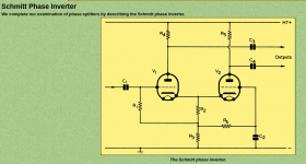
Some leak-through between both PI grids could also be constructed mentally due to the grid-to-cathode capacitances, as the PI cathodes see half the swing of the sum of both signals, Anyway, the Schmitt PI is a proven design, done by the millions. Hence: Why bother?
Best regards!
Best regards!
I'd never heard of the Schmitt phase-splitter, but I see it is nothing other than the long-tailed-pair (image attached.)...the Schmitt PI is a proven design, done by the millions.
Yes, I agree, Leo Fender's version is a botched-up long tailed pair.
I understand your viewpoint - why waste time chasing a mistake? It's obviously a mistake, so why not do the logical thing and just ignore it?...Why bother?
If I ever build a tube amp with a LTP phase splitter, that's exactly what I'll do - ignore Leo's mistake.
However, there is a legend out there that Leo's mistake is not a mistake at all, but rather some magical improvement over the textbook version. "It's a feature, not a bug", as the joke about Microsoft products goes.
I've come across this legend repeatedly, but I don't believe it. It would be nice to have some objective data I could point to.
-Gnobuddy
Attachments
Last edited:
Sorry, no, that's not exactly what I've meant. I wanted to say: Why bother with possible interferences between both grid signals?
And I'd also eradicate Leo's mistake 😉.
Best regards!
And I'd also eradicate Leo's mistake 😉.
Best regards!
I fixed the mistake I was making in my simulation (a tiny drawing error, trace that didn't actually connect to the resistor symbol it went to.)
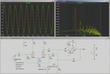
A little introduction regarding the simulation in the attached screenshot:
1) I used Derk Reefman's SPICE valve models for the 12AT7 (ECC81). Reefman's models seem to be among the best SPICE models for valves that are available.
2) For simplicity, I replaced the push-pull 6V6, OT, and associated components with an op-amp. I adjusted the voltage gain of the op-amp so that there is 6 dB of negative feedback when connected the same way Leonidas did. I'm guessing at how many dB of feedback is in the real Bassman - but it can't be too far off from 6 dB, probably within a couple of dB either way. If I got the amount of overall feedback right, this means the op-amp circuit now has the same voltage gain as the 6V6 pair along with its OT.
3) To keep the op-amp from clipping in the simulation, I increased its supply voltage to +/- 30 volts. A real OP-07 cannot withstand this much supply voltage, but the LTSpice model doesn't know about excessive power supply voltage.
4) Resistors R14 and R15, along with the .param and .step SPICE commands, act like an SPDT switch. At any given time, one of them has a resistance of one milli-ohm, while the other has a resistance of ten million ohms. These values are swapped when the ".step param k" statement is executed.
So the effect is to switch the 22k tail resistor either to ground (the proper "textbook" location), or to the top of the 100 ohm resistor (where Leonidas connected it.)
5) Input signal is 4 volts peak-to-peak, or 2 volts peak, or 1.414 volts RMS, 300 Hz, sinewave. (This is just below the threshold where the op-amp clips due to output current limiting, from trying to drive the 820 ohm feedback resistor.)
6) The green trace shows the output voltage when the feedback is applied properly. The yellow-brown trace shows the result of Leo's screw-up. As predicted, the effect of Leo's mistake is to very slightly reduce the amount of negative feedback, and therefore very slightly increase the voltage gain of the Bassman. The yellow-brown trace has very slightly more amplitude than the green one.
7) The FFT shows a minor change in 3rd-harmonic distortion. However this is 50 dB down from the fundamental, and therefore not audible.
All other harmonics are at least 65 dB down from the fundamental, and completely inaudible.
8) I see no evidence to suggest Leo's feedback connection does anything special. This lends credence to the idea that it was either a mistake, or a convenient way to re-use existing turret-boards with the newly redesigned schematic.
About now, somebody will probably say "Leo's magic mojo only happens when you include the 6V6s!", and we will be back to square one again...
-Gnobuddy
Attachments
What is the change in the 2nd harmonic?
I'm not in a mood to analyze this now (I did but many years back), so ignore me.
But you have taken one of the two outputs of the splitter. To a first approximation they ARE equal. BUT injecting a single-ended NFB signal into the common-mode input (the tail) is liable to have +/- effects different in each plate.
The "fake output stage" can be a differential-input amplifier. PSpice has several function-blocks to do such work without abusing or complicating "real" parts; Mooley may know the LTspice way. (Don't assume the single opamp diff-amp is OK, it has different impedances for different drives.)
There isn't any 2nd harmonic to be seen in this sim - it's buried in the FFT noise floor, 90 dB below the fundamental.What is the change in the 2nd harmonic?
A balanced LTP cancels out even harmonic distortion from the two devices, so this isn't too surprising. In LTSpice the balance is (unnaturally) perfect, and so there will be perfect cancellation of even harmonics.
Since the two devices are (ideally) matched, I would expect that anything injected at the shared cathodes will appear identically at each anode - this is just a perfectly ordinary common-mode signal, after all.BUT injecting a single-ended NFB signal into the common-mode input (the tail) is liable to have +/- effects different in each plate.
We can apply the usual principle of linear superposition to the two devices in the LTP, in particular, the one that's being a fed a feedback signal at both its cathode and its grid. Both signals are in phase, so the net effect is to reduce Vgk a tiny bit, effectively reducing the amount of feedback just a hair, and thereby increasing closed-loop voltage gain a hair.
How big a hair? The LTSpice simulation shows it's pretty small. Compare the amplitudes of the green and yellow-brown sine wave signals. The difference is too small to read precisely, but a quick approximations is that one signal (green) has a peak value of about 9V, the other about 9.5. That's about a 5% increase in closed-loop voltage gain when Leo's "special" feedback is implemented.
(5% is well below the minimum audible change of 1 dB, which is 12%. Too small to hear. Leo-feedback makes no audible difference.)
Without using Spice, we can make a rough estimate of the same thing as follows: impedance at the cathode of one 12AT7 should be (1/gm) + (ra/mu) + (Ra/mu). The first term is about 250 ohms, the second one another 250 ohms, the third about 1.5 kilo ohms. Total 2 kilo ohms; in parallel with the same impedance from the second triode, back down to about 1k small-signal impedance at the cathode.
With the signal fed to the bottom end of the 22k tail resistor, that means ~(1/23) of the feedback signal - call it 4% - makes it through the tail resistor to appear as a change in cathode voltage at the triodes.
So we have an amp with only a few decibels of negative feedback to start with, and then a tiny fraction of that already-small NFB (about 4% of it) is applied to the cathodes in Leo's scheme. Net result, the negative feedback signal is reduced by about 4%.
One would expect that this would result in about a 4% increase in closed-loop voltage gain, which is about one-third of a decibel. Well below the minimum 1 dB change detectable by human ears.
That 4% back-of-the-envelope estimation is gratifyingly close to the roughly 5% change seen in the LTSpice simulation, no?
I could do the classic three op-amp instrumentation amplifier circuit. But it may be just as easy to throw a pair of 6V6GT in the simulation - they're included in the Derk Reefman LTSpice tube library.Don't assume the single opamp diff-amp is OK, it has different impedances for different drives.
The other question is what that does to simulation run-times on my ageing Core i5 PC, but I guess we shall see!
-Gnobuddy
Thank you for everything.
We appreciate your hard work let's do it with tubes since it will always be a point of discord, at least it will be fixed.
I feel you about the aging hardware, on my laptop i sometime use older versions of programs that run better....
We appreciate your hard work let's do it with tubes since it will always be a point of discord, at least it will be fixed.
I feel you about the aging hardware, on my laptop i sometime use older versions of programs that run better....
Since the two devices are (ideally) matched, I would expect that anything injected at the shared cathodes will appear identically at each anode - this is just a perfectly ordinary common-mode signal, after all.
We can apply the usual principle of linear superposition to the two devices in the LTP, in particular, the one that's being a fed a feedback signal at both its cathode and its grid. Both signals are in phase, so the net effect is to reduce Vgk a tiny bit, effectively reducing the amount of feedback just a hair, and thereby increasing closed-loop voltage gain a hair.
IMHO we can also look at that thang as follows: As in Leo's interpretation the 2nd triode's grid grounding capacitor returns to the same point where the NFB signal is injected, instead of GND, this triode doesn't see any NFB signal at all. Hence, NFB applies to the input triode solely.
As some, including me, said before: Returning the tail resistor (or CCS) to GND directly makes everything much clearer.
Best regards!
Best regards!
Remember that Leo Fender was no technician or guitarist at all, but just a salesman. Hence, his ability of understanding tube circuitry surely wasn't extraordinary. Instead he cobbled together what he found in application notes and tube books.
When some famous guitarists discovered that his Bassman amplifer sounded georgeously when overdriven, a great demand was concieved all of a sudden, especially in Great Britain. As import taxes were almost prohibitively high in those days, the next one to jump on was British James Marshall. He simply copied the Bassman schematics for his first generation of amplifiers, but he had to replace the tubes and the transformers by British products (Mullard, G.E.C., Dagnall resp.). The Marshall that was made famous by Jimi Hendrix (or was it vice versa? I don't know really…) basically was a Bassman with two pairs of KT66's, working on two Dagnall output transformers, and feeding two speaker cabinets.
And the story continues…
Best regards!
The plot thickens!
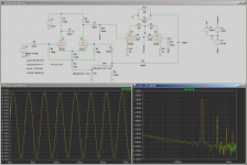
Here is the LTSpice simulation of the entire power section of the Bassman, including a pair of 6L6GC biased to 40 mA each.
Keep in mind this is a simulation, not reality - results are only as good as the tube models. I'm using the Derk Reefman models, which are said to be perhaps the most accurate ones available now. Still, this is only a simulation, and we should all keep that in mind.
A few interesting points:
1) Adding the 6L6 output tubes brings back 2nd harmonic distortion, as it should; Schade's white-paper on the 6L6 explicitly mentions that beam power tubes tend to produce lots of 2nd harmonic distortion compared to otherwise-similar pentodes.
(But why doesn't the 2nd harmonic distortion cancel out in the push-pull output stage? It's a simulation, so everything is perfectly matched.)
2) There is now even less change in output amplitude (and closed-loop voltage gain) when switching between textbook negative feedback, and weird Leo-feedback. The difference is so small that it's completely negligible - it's barely detectable on the plot, and would be completely inaudible (far less than 1 dB change).
There is about 6 dB of overall negative feedback, as before; I did nothing to ensure this, other than assume a 4-ohm speaker, and set up the transformer turns-ratios to present 8k anode-to-anode load to the 6L6s. That done, the voltage gain drops to about half when the NFB is connected.
3) FWIW, the FFT shows that Leo-feedback reduces 2nd harmonic distortion compared to proper feedback. But - it goes from completely inaudible (1%, 40 dB below the fundamental) to even more completely inaudible (0.3%, 50 dB below the fundamental.)
In the era of carefully controlled audio tests done by trained professionals, there was some doubt as to whether 1% THD could be heard or not; some people could detect it using a pure sine-wave test tone, statistics were inconclusive as to whether anyone could detect it listening to music. I'll bet my hat there is zero chance of anybody detecting 1% THD using an electric guitar as the test signal.
The Bassman's preamp would have been generating considerably more distortion at some control settings, and that certainly could be heard. But if this LTSpice simulation is close to correct, the power section of the Bassman was squeaky-clean, Hi-Fi clean, no-audible-distortion clean. No matter whether using Leo-feedback, or proper textbook-feedback.
-Gnobuddy
Attachments
- Home
- Live Sound
- Instruments and Amps
- Phase inverter feedback location